Method and apparatus for removing heat

a technology of heat removal and cooling method, applied in the direction of cooling apparatus, lighting and heating apparatus, instruments, etc., can solve the problems of insufficient heat dissipation of silicon heat poorly, design engineers will end up sacrificing performance and power for lower temperatures and stability, and silicon will end up wasting heat energy

a technology of heat removal and cooling method, applied in the direction of cooling apparatus, lighting and heating apparatus, instruments, etc., can solve the problems of insufficient heat dissipation of silicon heat poorly, design engineers will end up sacrificing performance and power for lower temperatures and stability, and silicon will end up wasting heat energy

US20060090474A1Inactive Publication Date: 2006-05-04INTEL CORP

Image

  • Method and apparatus for removing heat
  • Method and apparatus for removing heat
  • Method and apparatus for removing heat

Examples


Embodiment Construction

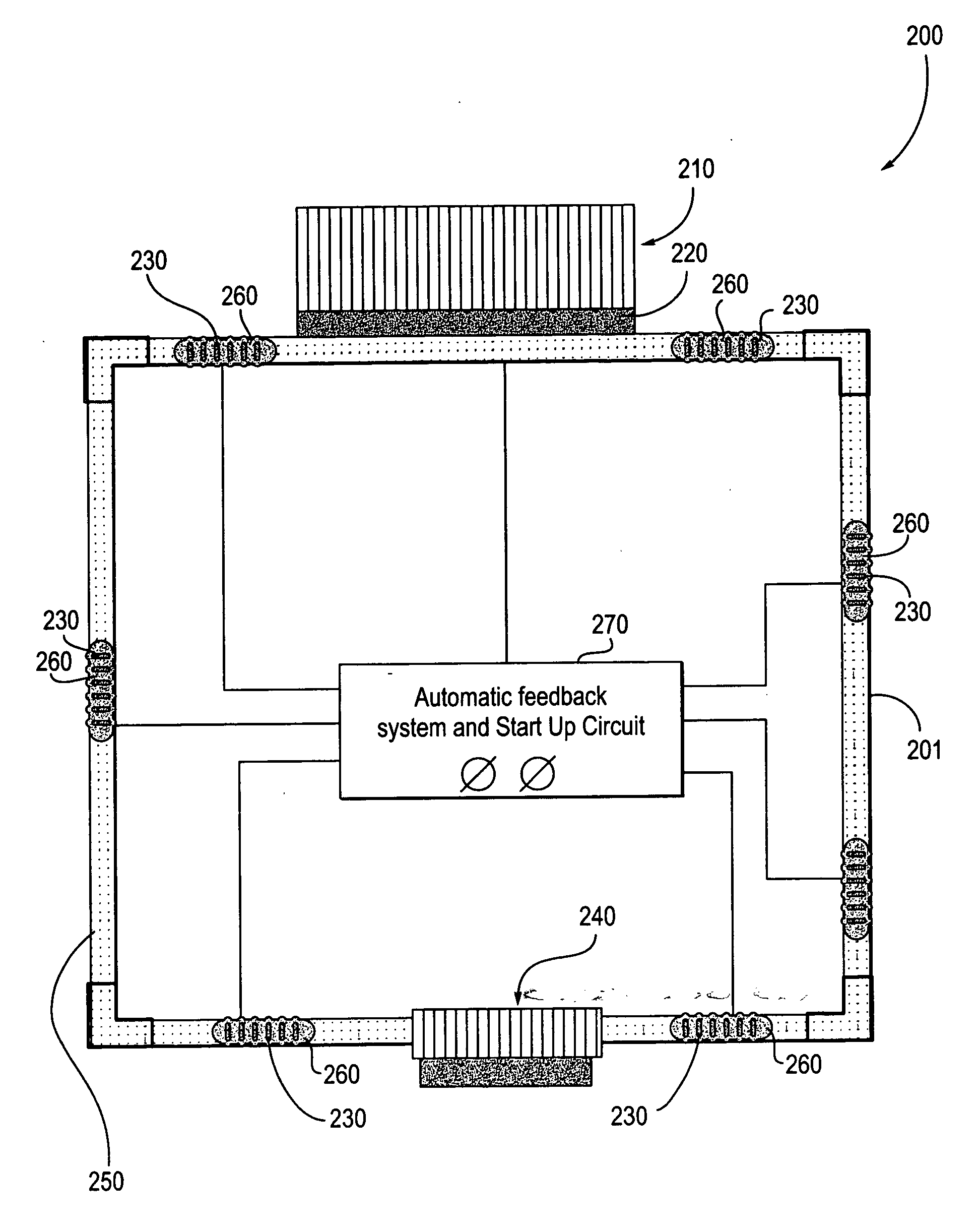
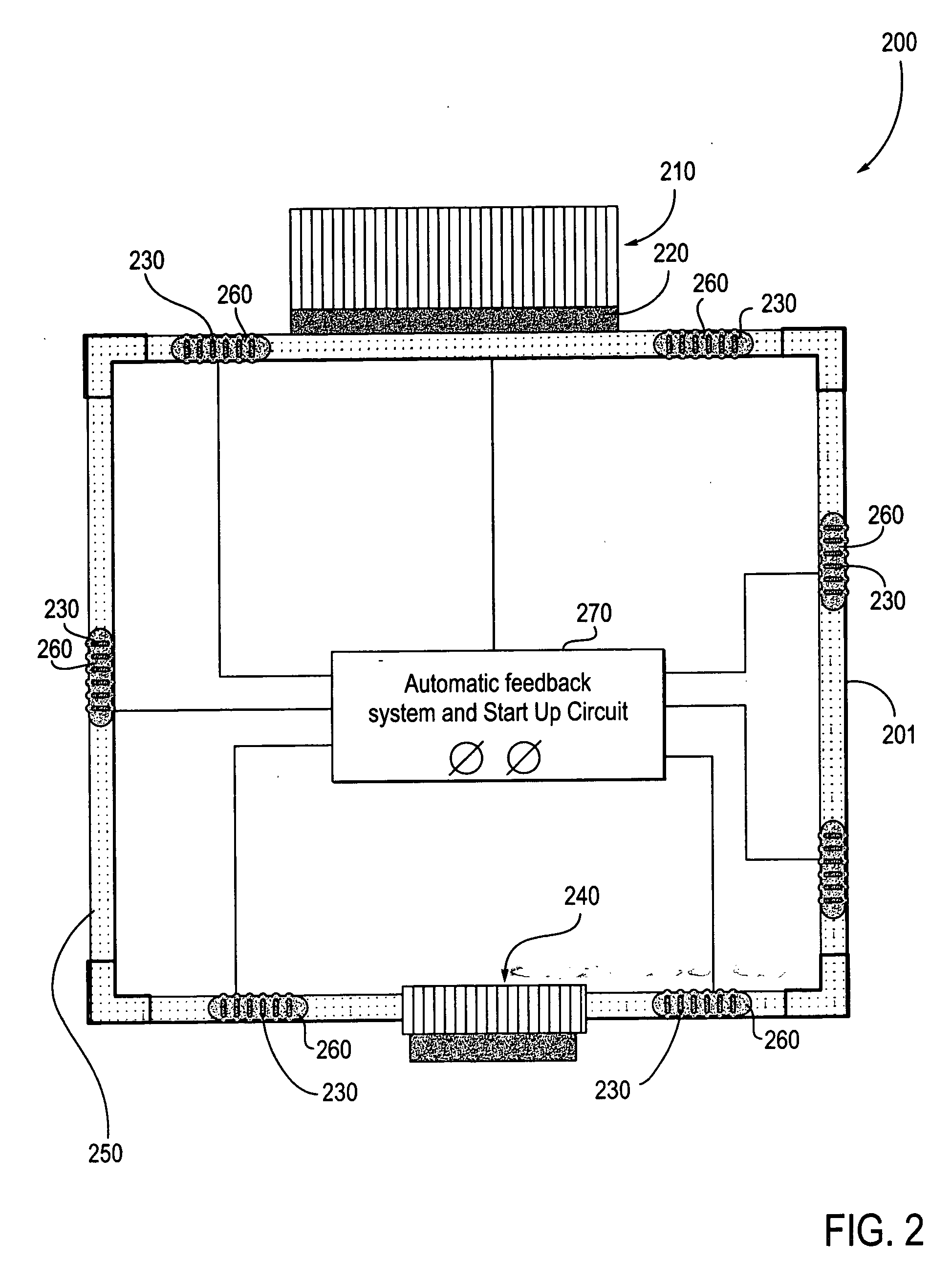
[0024] The embodiments discussed herein generally relate to device cooling using ferrofluid pumping of liquid metal flowing over a die combined with thermoelectrics for refrigeration type performance without using a compressor. Ferrofluids are used to help with pumping of the liquid metal. Referring to the figures, exemplary embodiments will now be described. The exemplary embodiments are provided to illustrate the embodiments and should not be construed as limiting the scope of the embodiments.

[0025] Reference in the specification to “an embodiment,”“one embodiment,”“some embodiments,” or “other embodiments” means that a particular feature, structure, or characteristic described in connection with the embodiments is included in at least some embodiments, but not necessarily all embodiments. The various appearances of “an embodiment,”“one embodiment,” or “some embodiments” is not necessarily all referring to the same embodiment. If the specification states a component, feature, str...


PUM


Abstract

A device includes a liquid metal and a ferrofluid contained in a closed tube. Many electrode groups are connected to the closed tube. A feedback device is connected to the electrode groups. The feedback device switches power to each electrode group in series to circulate the liquid metal and move the ferrofluid in the closed tube.

Description

BACKGROUND [0001] 1. Field [0002] The embodiments relate to cooling by removing heat, and more particularly to removing heat of a device using forced convection liquid metal combined with thermoelectric and a ferrofluid. [0003] 2. Description of the Related Art [0004] Cooling is one of the main concerns for computer and processor manufacturers and developers. The industry depends on functional cooling techniques to help cool their rapidly advancing chips, which tend to run hotter and hotter. Without proper cooling, design engineers will end up sacrificing performance and power for lower temperatures and stability. [0005] Initially, passive cooling was enough to keep central processing units (CPUs) in a stable state. As chips evolved, however, so did cooling due to necessity. A transition from aluminum and copper to graphite heat sinks, and from passive to active cooling (i.e., using a fan to force out the heat that dissipates into the CPUs surrounding airflow) has kept pace with the...

Claims


Application Information

Patent Timeline
04 May 2006
Publication
US20060090474A1
IPC
F25B21/02; F28D15/00; F25D23/12
CPC
F28D15/00; G06F1/20; G06F1/206; H01L23/473; H01L2924/0002; H01L2924/00
Inventors
SAUCIUC, IOAN; WILLIAMS, JIM D.