Dehumidification system with multiple condensers and compound compressor

a technology of condensers and compressors, applied in the direction of positive displacement liquid engines, heating types, lighting and heating apparatus, etc., can solve the problems of insufficient utilization, unfavorable lowering of air temperature below certain levels, and challenges for refrigerant system designers

Inactive Publication Date: 2006-05-04
CARRIER CORP
View PDF17 Cites 3 Cited by
  • Summary
  • Abstract
  • Description
  • Claims
  • Application Information

AI Technical Summary

Benefits of technology

[0007] In the proposed system design, a portion of the refrigerant, compressed to some intermediate pressure, leaves the compressor through an intermediate compressor port, while the rest of the refrigerant vapor continues through the compression process to a main discharge port and then to a first (main) condenser. The refrigerant that leaves the intermediate port is connected to another (second) condenser. Consequently, for such a system an additional temperature level of heat rejection is available. Such heat rejection capability at various temperature levels can be utilized in multiple industrial applications where condensers are located in different environments. For example, the main condenser can be located outdoors, while the second condenser is located indoors. Another application would be for heat pump installations, where there are two environmental chambers each requiring a different amount of heating. The amount of refrigerant flowing through each condenser can be regulated by expansion devices, as explained below. In the present invention, a refrigerant system is provided with a common evaporator receiving refrigerant from at least two condensers. The evaporator is associated with one or more reheat coils.

Problems solved by technology

However, lowering the air temperature below certain level is undesirable.
This has presented challenges to refrigerant system designers.
While reheat coils have been incorporated into air conditioning systems, they have not been utilized in an air conditioning system having an ability to reject heat at multiple temperature levels.

Method used


Image

  • Dehumidification system with multiple condensers and compound compressor
  • Dehumidification system with multiple condensers and compound compressor
  • Dehumidification system with multiple condensers and compound compressor

Examples


Embodiment Construction

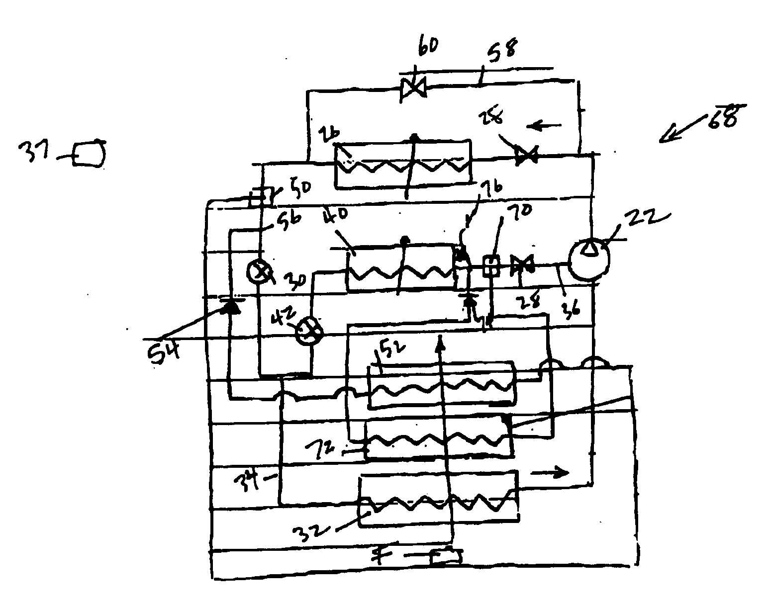
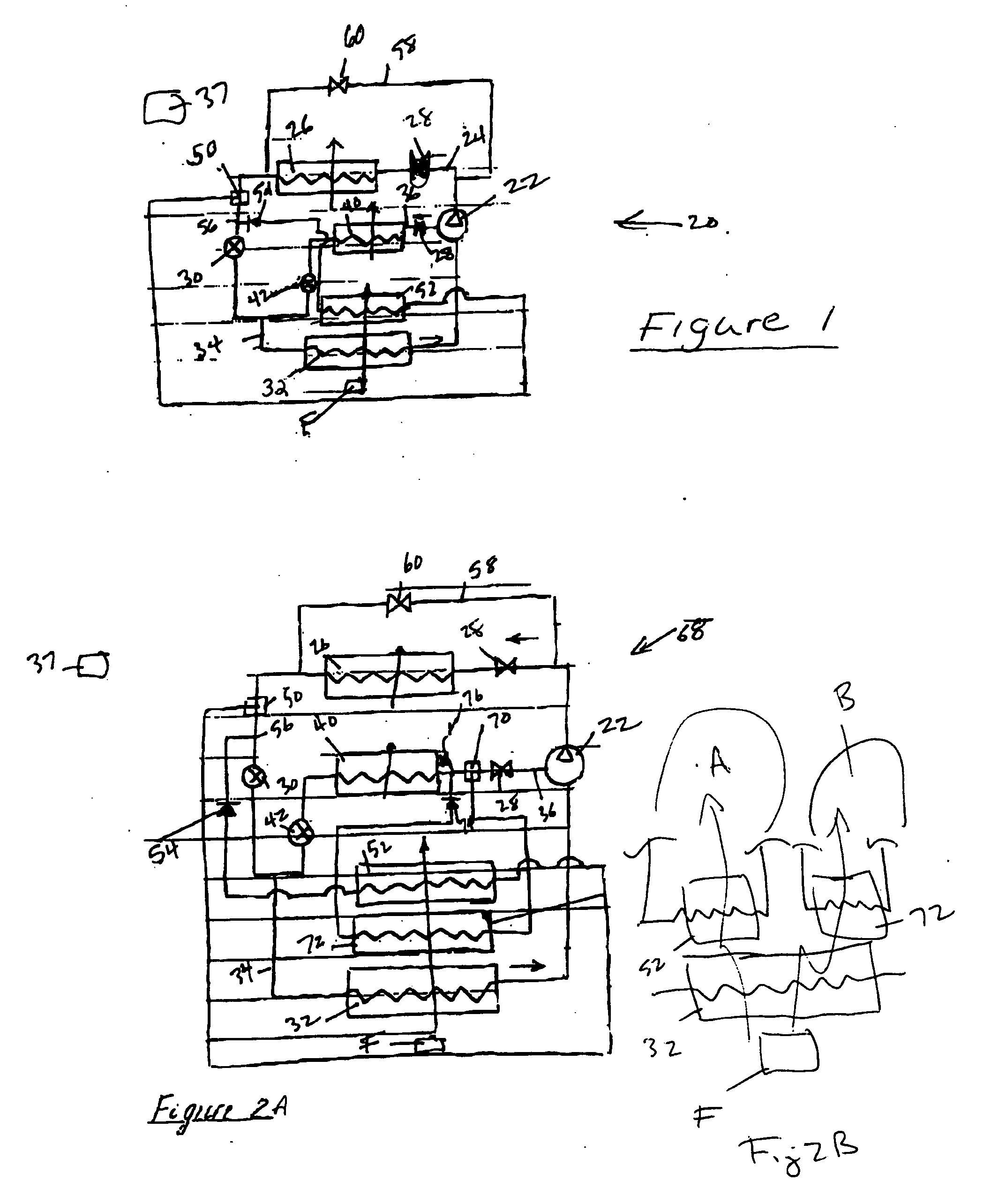
[0018]FIG. 1 shows a refrigerant system 20 having a single compressor 22 delivering compressed refrigerant to a discharge line 24. Discharge line 24 communicates with a first condenser 26. Refrigerant passes through an optional shut-off valve 28, through the condenser 26 and then through an expansion device 30. At a connection 34, refrigerant is received downstream of the expansion device 30, and delivered to an evaporator 32. The refrigerant from the evaporator 32 returns to the compressor 22. An intermediate pressure tap line 36 passes through an optional shut-off valve 28, and delivers an intermediate pressure refrigerant to a second condenser 40. The shut-off valve 28 can be closed if under some operating conditions there is a need to route all of the refrigerant entering the compressor 22 through a discharge line 24. Otherwise, the shut-off valve 28 would normally be open. An expansion device 42 is positioned downstream of condenser 40. The refrigerant would be at a distinct te...


PUM


Abstract

A refrigerant cycle is provided with a multi-port compressor or compressor stages connected in series, and multiple condensers. A single evaporator communicates with the plurality of condensers. At least one of the plurality of condensers receives fully compressed refrigerant while the other condensers receive refrigerant at intermediate pressure. A control can optionally direct refrigerant to the condensers to achieve desired system heat rejection characteristics and operating conditions. One or multiple reheat coils may be associated with the evaporator and are arranged either in series or in parallel to provide a desired dehumidification function and reheat stages. One or several of the intermediate pressure condensers may be utilized for the reheat function as well.

Description

BACKGROUND OF THE INVENTION [0001] This application relates to a refrigerant system having a common evaporator, but separate condensers where at least one of the condensers is connected to an intermediate pressure compression stage, while the other condenser is connected to a high pressure compression stage, and wherein a reheat coil is incorporated into the refrigerant cycle. [0002] Refrigerant systems are utilized in applications to change the temperature and humidity or otherwise condition the environment. In a standard refrigerant system, a compressor delivers a compressed refrigerant to a heat exchanger, known as a condenser, which is typically located outside. From the condenser, the refrigerant passes through an expansion device, and then to an indoor heat exchanger, known as an evaporator. At the evaporator, moisture may be removed from the air, and the temperature of air blown over the evaporator coil is lowered. From the evaporator, the refrigerant returns to the compresso...

Claims


Application Information

Patent Timeline
Patent Type & Authority Applications(United States)
IPC IPC(8): F25B29/00F25B39/02F25B41/00
CPCF24F3/153F25B1/10F25B6/00F25B41/04F25B2400/0403F25B41/20F25B41/24
Inventor TARAS, MICHAEL F.LIFSON, ALEXANDER
Owner CARRIER CORP
Why Eureka
Try Eureka