Eureka AIR delivers breakthrough ideas for toughest innovation challenges, trusted by R&D personnel around the world.

A circular flow energy-saving smokeless oven

A circulating flow and oven technology, which is applied in the field of circulating flow energy-saving smokeless ovens, can solve the problems of large heat loss, environmental pollution, single function, etc., and achieve the effect of reducing power consumption

Active Publication Date: 2017-07-28
KUNMING UNIV OF SCI & TECH
View PDF6 Cites 3 Cited by
  • Summary
  • Abstract
  • Description
  • Claims
  • Application Information

AI Technical Summary

Problems solved by technology

[0010] Aiming at the disadvantages of large heat loss, single function, and environmental pollution in the above-mentioned existing barbecue equipment, the present invention provides a circulating flow energy-saving smokeless oven

Method used


Image

  • A circular flow energy-saving smokeless oven
  • A circular flow energy-saving smokeless oven
  • A circular flow energy-saving smokeless oven

Examples


Embodiment 1

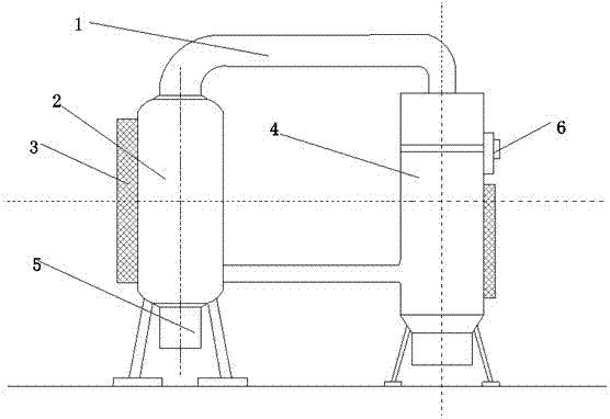
[0037] Such as figure 1 As shown, the circulating flow energy-saving smokeless oven includes a double circulation system 1, a main oven 2, a grill system 3, an auxiliary oven 4, a bio-grease collector 5 and a power supply device 6; the main oven 2 passes The double circulation system 1 communicates with the auxiliary oven 4, the main oven 2 and the auxiliary oven 4 are provided with a grill system 3, the collection platform at the bottom of the main oven 2 and the auxiliary oven 4 is connected to the bio-grease collector 5, and the power supply device 6 is installed on the side of the auxiliary oven 4 to provide electric energy. The temperature of the upper and middle parts of the main oven 2 is higher than that of the lower part, and the temperature of the upper and middle parts of the auxiliary oven 4 is lower than that of the lower part.

Embodiment 2

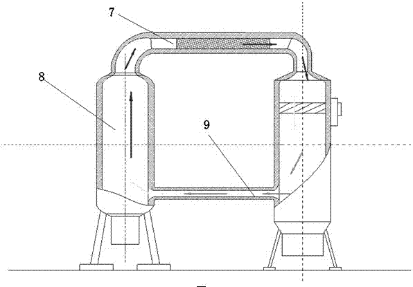
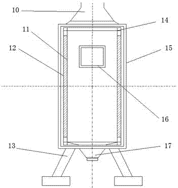
[0039] Such as figure 1 As shown, the circulating flow energy-saving smokeless oven includes a double circulation system 1, a main oven 2, a grill system 3, an auxiliary oven 4, a bio-grease collector 5 and a power supply device 6; the main oven 2 passes The double circulation system 1 communicates with the auxiliary oven 4, the main oven 2 and the auxiliary oven 4 are provided with a grill system 3, the collection platform at the bottom of the main oven 2 and the auxiliary oven 4 is connected to the bio-grease collector 5, and the power supply device 6 is installed on the side of the auxiliary oven 4 to provide electric energy. The temperature of the upper and middle parts of the main oven 2 is higher than that of the lower part, and the temperature of the upper and middle parts of the auxiliary oven 4 is lower than that of the lower part.

[0040] The main oven 2 includes a horn smoke exhaust port 10, a high-power infrared electric heating tube 11, a fly ash foam brick 12, a...


PUM


Abstract

The invention relates to a circular flow energy-saving smokeless oven and belongs to the technical field of barbecue devices for civil use. The oven comprises a double-circulation system, a main oven, a grill system, an auxiliary oven, a biological oil collector and a power supply device. The main oven communicates with the auxiliary oven via the double-circulation system; the grill system is arranged on the main oven and the auxiliary oven; collection stands at the bottoms of the main oven and the auxiliary oven are connected with the biological oil collector; the power supply device is installed on a side surface of the auxiliary oven for providing power; the temperature of the upper portion and the temperature of the middle portion of the main oven are higher than the temperature of the lower portion; the temperature of the upper portion and the middle portion of the auxiliary oven are lower than the temperature of the lower portion. The circular flow energy-saving smokeless oven has the advantages of high heat energy utilization rate, high efficiency, cleanness, convenient and low cost and is a device for civil cooking which can be used for continuous large-scale barbecue.

Description

technical field [0001] The invention relates to a circulating flow energy-saving smokeless oven, which belongs to the technical field of civil barbecue equipment. Background technique [0002] In the barbecue equipment industry, especially in ordinary open-air barbecues, many ovens on the market use coal as a heat source, which can easily lead to carbon monoxide poisoning, and the smoke and dust produced can easily cause cancer and cause safety and hygiene problems. Many ovens are generally outdoor barbecues without recycling flue gas waste heat and waste liquid, and incomplete combustion of coal, lack of insulation layer, and a large amount of heat lost to the air, all of which lead to a significant increase in energy consumption of the oven. Many ovens emit exhaust gas directly to the air, causing air pollution. [0003] Most ovens are aimed at heating and roasting food, but cannot take into account environmental protection and waste recycling. There are many problems in...

Claims


Application Information

Patent Timeline
IPC IPC(8): A47J37/07
CPCA47J37/0722A47J37/0786
Inventor 肖丁天卿山
Owner KUNMING UNIV OF SCI & TECH
Why Eureka
Eureka Blog
Learn More