Device for driving an output mechanism

Inactive Publication Date: 2006-05-04
HOUBEN JAN PETER
View PDF8 Cites 0 Cited by
  • Summary
  • Abstract
  • Description
  • Claims
  • Application Information

AI Technical Summary

Benefits of technology

[0004] With the devices according to the invention for driving an output mechanism with a rotationally driveable input shaft, in the case of which means are located between the input shaft and the output mechanism for transmitting a drive torque of the input shaft to the output mechanism, and a non-positive functional connection can be created between a first means and the output mechanism, enabling an alternating movement of the first means into be converted into a movement of the output mechanism, the drivi

Problems solved by technology

The disadvantage of this, however, is the fact that the use of gear wheels translates into high production costs in the fabrication of th

Method used


Image

  • Device for driving an output mechanism
  • Device for driving an output mechanism
  • Device for driving an output mechanism

Examples


Example

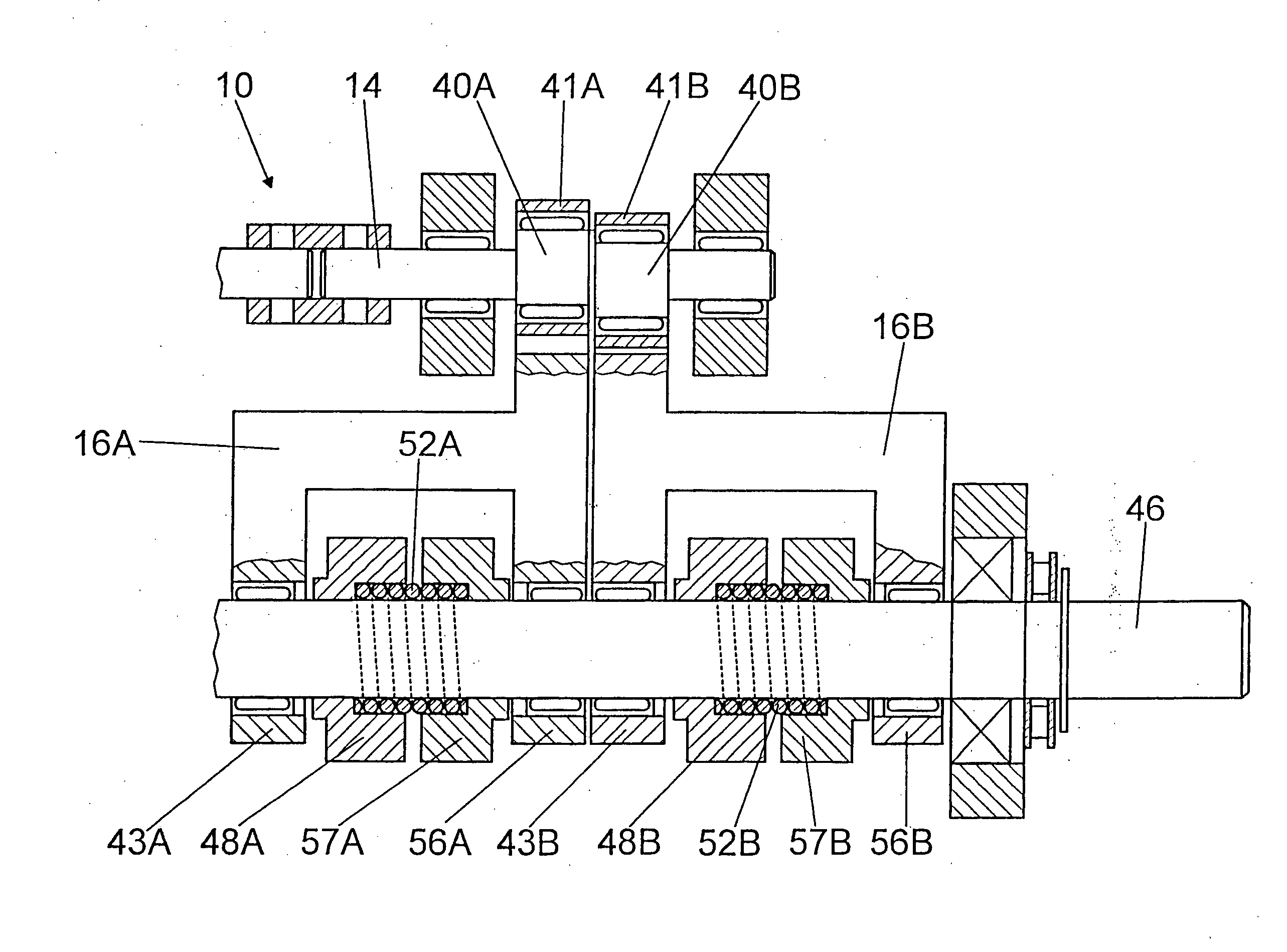
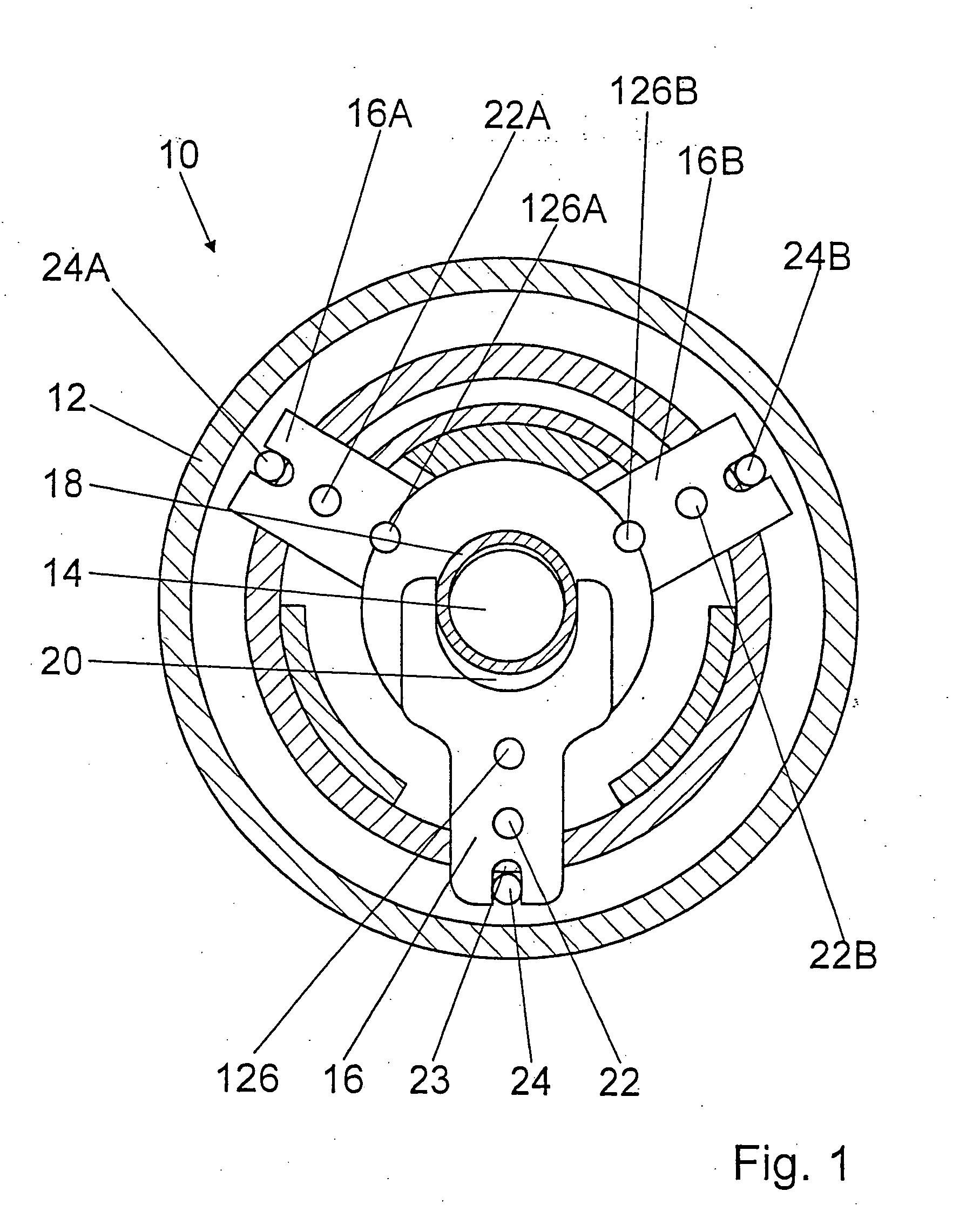
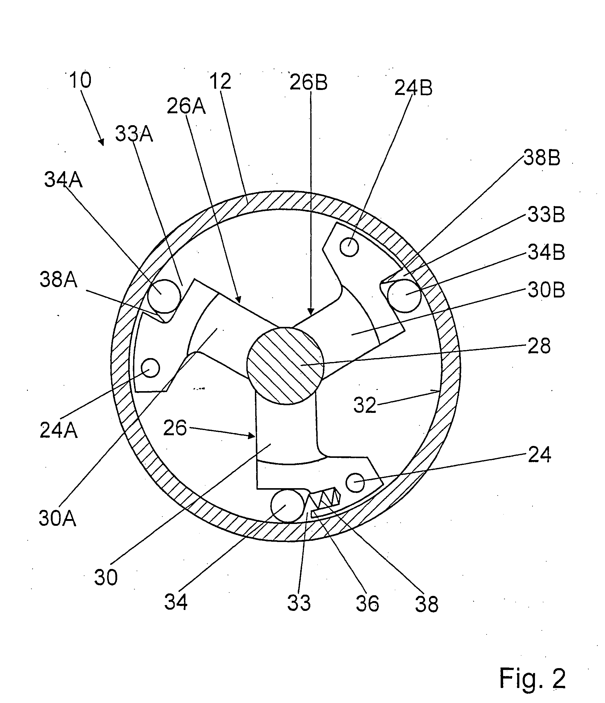
[0015]FIGS. 1 and 2 show a device 10 for driving an output mechanism via an annular body 12, comprising a rotationally driveable input shaft 14 of the device 10 that serves simultaneously as the output shaft of a not-shown electric motor. Means for transmitting a drive torque of the input shaft 14 to the output mechanism or the annular body 12 installed upstream from the output mechanism are located between the input shaft 14 and the output mechanism.

[0016] A non-positive functional connection can be created between a first means 16 configured as oscillating crank and the output mechanism, by means of which an alternating movement of the oscillating crank 16 can be converted into a plurality of successive movements or rotational movements of the output mechanism in one direction, whereby the multiple movements effect a continuous operation of the output mechanism. In addition to the first oscillating crank 16, two oscillating cranks 16A and 16B of identical design are situated at 1...


PUM

PropertyMeasurementUnit
Forceaaaaaaaaaa
Ratioaaaaaaaaaa
Torqueaaaaaaaaaa

Abstract

A device for driving an output mechanism has a rotationally driveable input shaft, whereby elements are located between the input shaft and the output mechanism for transmitting a drive torque of the input shaft to the output mechanism, whereby a non-positive functional connection can be created between a first element and the output mechanism, enabling an alternating movement of the first element to be converted into a movement of the output mechanism, whereby the elements are configured such that the alternating rotational movement of the first element is capable of being converted into a translational movement of the output mechanism, wherein at least one lever element is turnably mounted on the first element, via which the lever element the first elements are functionally interconnected with at least one gripper element.

Description

PRIOR ART [0001] The invention relates to a device for driving an output mechanism with a rotating input shaft. [0002] Devices for driving an output mechanism with a rotating input shaft are made known in the prior art, said devices being used in drills, impact drills or the like. Devices of this type comprise a plurality of gear wheels between the input shaft and the output mechanism, which said gear wheels are provided for ratio-conversion purposes and form a non-positive connection between the input shaft and the output mechanism in order to transform a high rotational speed of the input shaft serving as drive into a lower frequency of motion or rotational speed of the output mechanism while simultaneously increasing the drive force to be transmitted to the output mechanism. [0003] The disadvantage of this, however, is the fact that the use of gear wheels translates into high production costs in the fabrication of the known devices, and, when used in drills, impact hammers or rot...

Claims


Application Information

Patent Timeline
IPC IPC(8): F16H29/00B23B45/16B23B47/04F16H29/02F16H29/08F16H31/00
CPCF16H29/02F16H29/08Y10T74/1508Y10T74/1598F16H31/008
Inventor HOUBEN, JAN PETER
Owner HOUBEN JAN PETER
Why Eureka
Try Eureka