Metal cutting band saw comprising a suspended saw frame

a technology of metal cutting band saw and saw frame, which is applied in the direction of metal sawing device, sawing apparatus, metal sawing apparatus, etc., can solve the problems of compact material flow direction in the new arrangement, and achieve the effect of easy to reach the miter angle, increase the size of the machine, and high robustness

Inactive Publication Date: 2006-05-04
DIENER MARK
View PDF4 Cites 10 Cited by
  • Summary
  • Abstract
  • Description
  • Claims
  • Application Information

AI Technical Summary

Benefits of technology

[0007] Since the swivel support is arranged above the workpiece, it is located in a region in which neither cutting compound nor chips accumulate. The sealing of the swivel support is thereby significantly simplified. The reduced risk of soiling also has very favorable effects on the service life and the swivel support accuracy. In addition, the novel arrangement is very compact in the material flow direction.
[0009] Depending on the design of the main carrier, it is possible to easily reach miter angles up to 30° without having to significantly increase the size of the machine in the longitudinal direction, i.e., in the direction of the material flow. In prior art sawing machines it is necessary to use a sector shaped turntable, with the sector angle of double miters corresponding to twice the possible miter angle. The dimensions of the support table itself thereby produce a machine of significant size.
[0010] The main carrier can be configured in two different ways. The main carrier can be in the form of a gantry or a gallows. The configuration in the shape of a gantry in particular is highly robust, since it is suitable for applications entailing extremely large cutting widths. In such a case, the distance between the uprights is preferably greater than the corresponding width of the saw frame, so that arbitrary adjustments of the miter position can be accomplished.
[0011] The gallows shaped configuration, in contrast, has the significant advantage that the support table for the workpiece is accessible from the side. Long workpieces that must be separated in a central region can be introduced into the machine from the side and need not be placed on and pushed through the machine longitudinally.
[0012] If the projecting beam of the gallows shaped configuration lies parallel to the material flow direction so that the upright is offset relative to the cutting position in the material flow direction, it is possible to produce miter position adjustments easily in both directions. On the other hand, the upright may be moved very close to the cutting point so that the projecting beam can be made relatively short. The uprights may be rigidly connected to the machine frame or mounted independently of it on a concrete foundation.

Problems solved by technology

In addition, the novel arrangement is very compact in the material flow direction.

Method used


Image

  • Metal cutting band saw comprising a suspended saw frame
  • Metal cutting band saw comprising a suspended saw frame
  • Metal cutting band saw comprising a suspended saw frame

Examples


Embodiment Construction

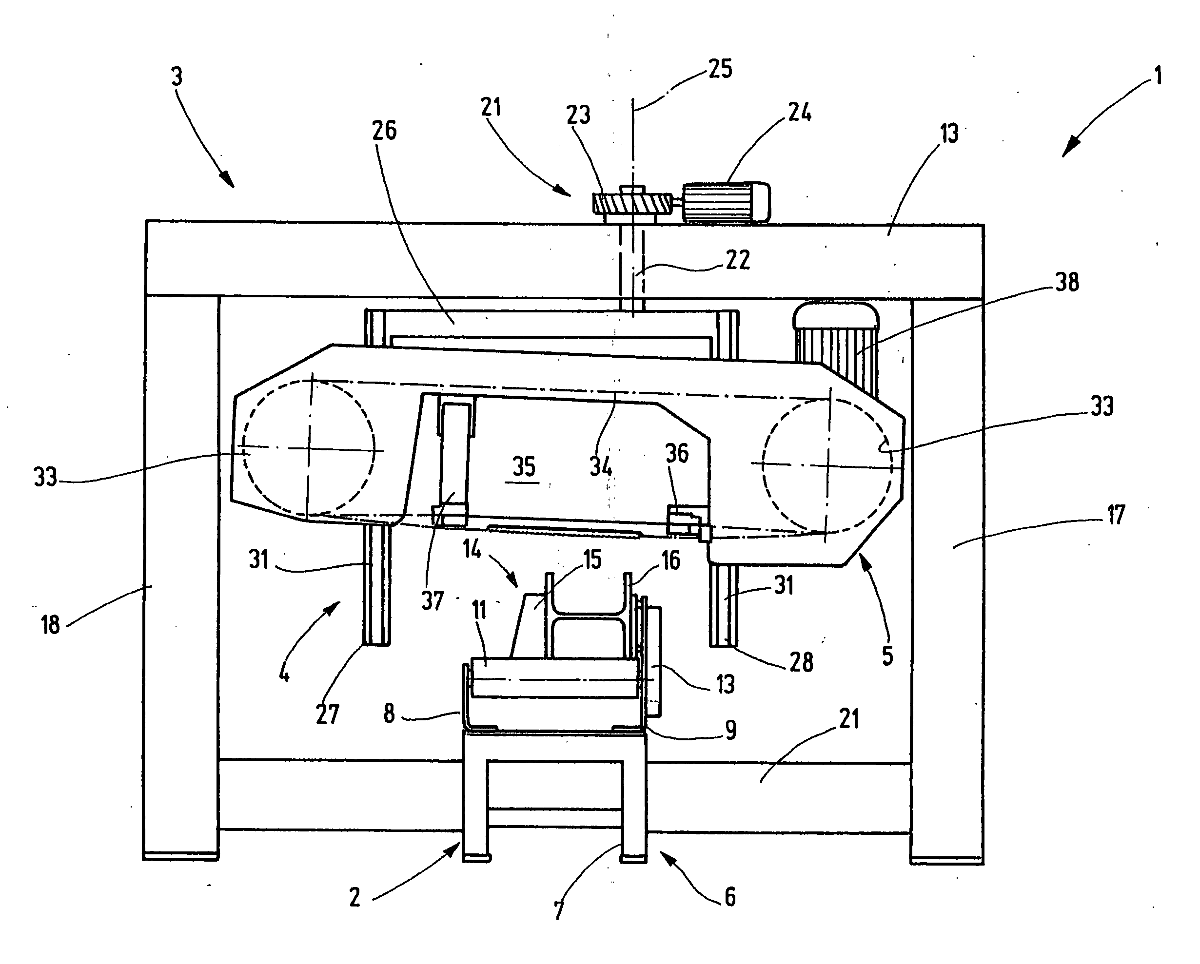
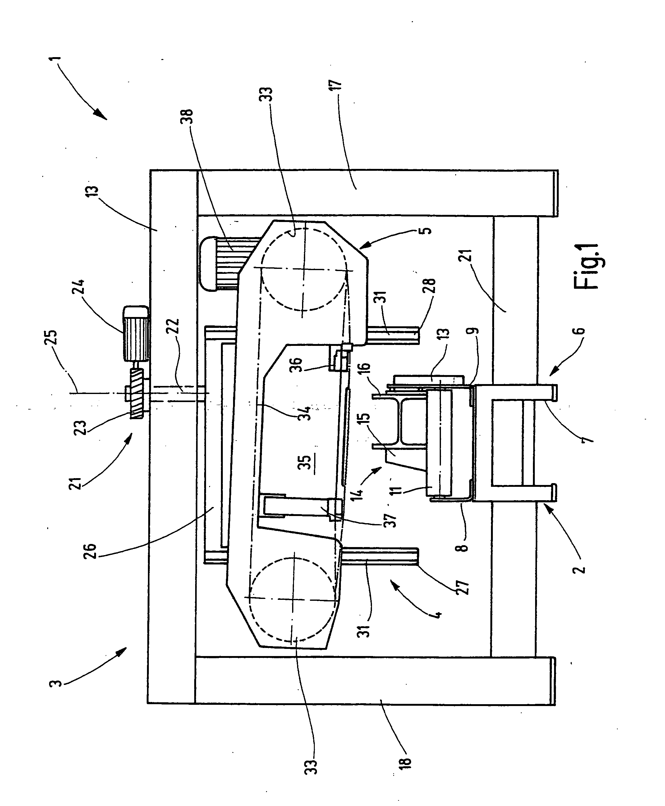
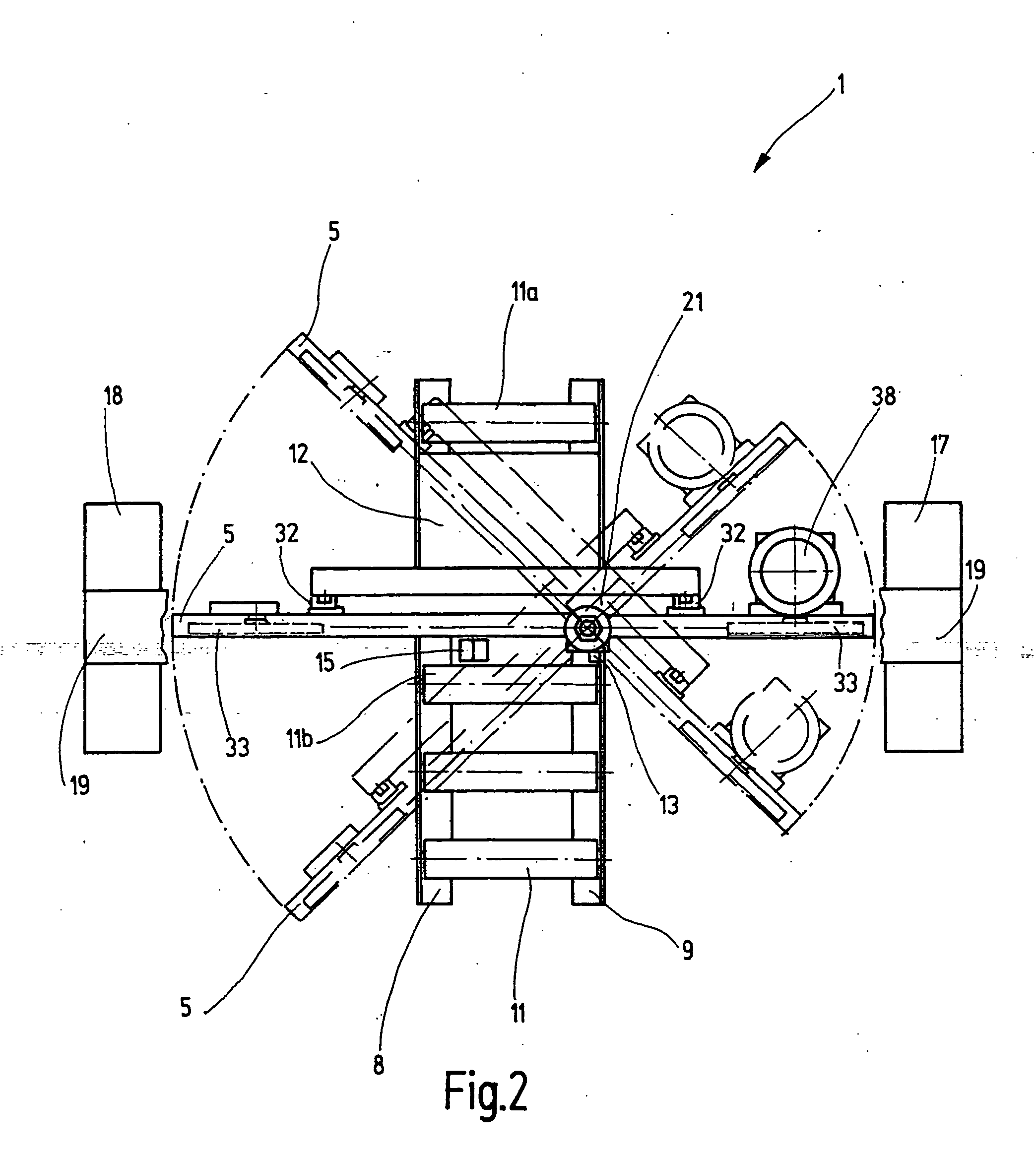
[0023]FIGS. 1 and 2 show a metal cutting band saw 1 according to the invention. The metal cutting band saw 1 has a machine frame 2, with a gantry shaped main carrier 3 that is mounted on the floor foundation spanning the machine frame. An intermediate carrier 4 that serves to hold a saw frame 5 is pivotally supported on the main carrier 3.

[0024] The machine frame 2 consists of a lower frame 6 with legs 7. Two angled profile rails 8 and 9 that extend continuously in the longitudinal direction are mounted on the upper side of the frame 6. Several rollers 11 that serve as a workpiece support are arranged axially parallel and adjacent to one another between the angled profile rails 8 and 9. The rollers 11 can rotate freely and their upper sides are tangent to an imaginary common plane. Between the rollers 11a and 11b, a plate like support table 12 lies on the lower frame 7 between the profile rails 8 and 9. In its initial state, the support table 12 has a flat, smooth surface that lies...


PUM

PropertyMeasurementUnit
distanceaaaaaaaaaa
heightaaaaaaaaaa
miter angleaaaaaaaaaa

Abstract

A metal cutting band saw is provided that includes a main carrier, on which an intermediate carrier is pivotally mounted. The saw frame, which can be adjusted in the direction of the workpiece, is mounted on the intermediate carrier by means of a swivel support or a parallel guide. The swivel support for connecting the main carrier to the intermediate carrier is located above the workpiece to be processed.

Description

FIELD OF THE INVENTION [0001] The present invention relates to metal cutting band saws, and in particular, to metal cutting band saws for mitering elongated workpieces. BACKGROUND OF INVENTION [0002] A metal cutting band saw with a machine frame on which the workpiece to be cut is placed is disclosed in DE 40 40 470 A1. The machine frame is provided with a vise for fixing the workpiece to be processed on the machine frame. The vise contains a stationary clamping jaw that also serves as a reference surface. A swivel support allows the saw frame in which the bandsaw blade is supported to move into different miter positions. The required swivel support is arranged underneath the plane of the workpiece and carries not only the saw frame but also a workpiece support table that serves to support the part of the workpiece that is subjected to the cutting process during sawing. The advantage of this arrangement is that the bandsaw blade does not produce a horizontal pivoting motion relative...

Claims


Application Information

Patent Timeline
Patent Type & Authority Applications(United States)
IPC IPC(8): B26D1/00B23D53/04
CPCB23D53/04B23D53/045B23D53/08Y10T83/95Y10T83/7126Y10T83/7201Y10T83/7208Y10T83/7133Y10T83/929Y10T83/7487
Inventor DIENER, MARK
Owner DIENER MARK
Why Eureka
Try Eureka