Vehicle switch

a technology for switching devices and vehicles, applied in the direction of switch lubrication, contact mechanisms, electrical appliances, etc., can solve the problems of insufficient water-proof and dust-proof inside of the switch, and achieve the effect of preventing the breakage of the elastic cover and small friction coefficien

Active Publication Date: 2006-05-04
PANASONIC CORP
View PDF4 Cites 4 Cited by
  • Summary
  • Abstract
  • Description
  • Claims
  • Application Information

AI Technical Summary

Benefits of technology

[0012] A vehicle switch of the present invention includes a case, an operating body, a switch contact, an elastic cover, and a sliding part. A through-hole is formed through the top face of the case. The top end of the operating body projects from the through-hole. The operating body is housed in the case vertically movable. The switch contact is brought into and out of electrical contact by vertical movement of the operating body. The elastic cover covers the through-hole of the case and the top end of the operating body. The sliding part that has a smaller friction coefficient than that of the elastic cover is provided in the top port

Problems solved by technology

However, used for water-proof and dust-proof cover 38 in the conventional vehicle switch is a rubber or other materials that has a large friction coefficie

Method used


Image

  • Vehicle switch
  • Vehicle switch
  • Vehicle switch

Examples


Embodiment Construction

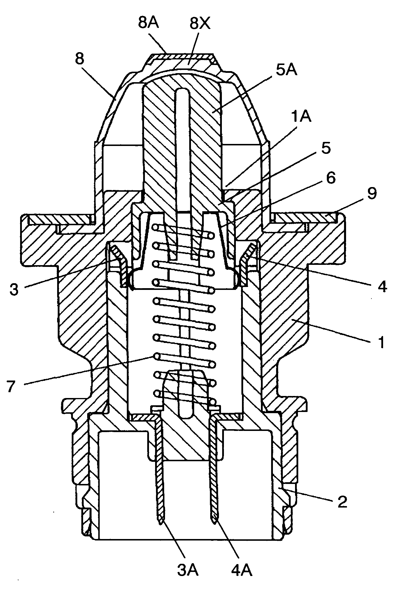
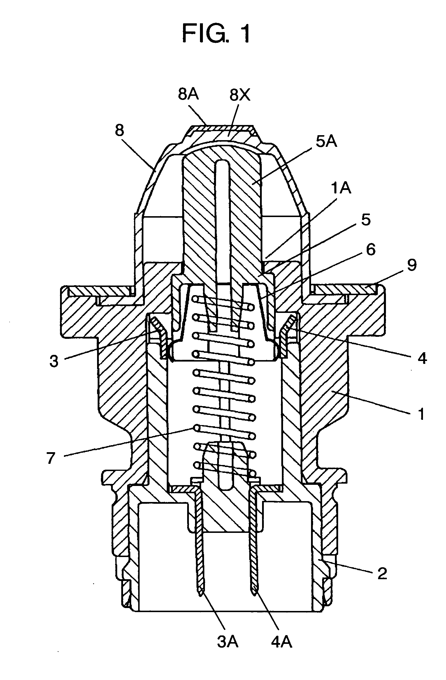
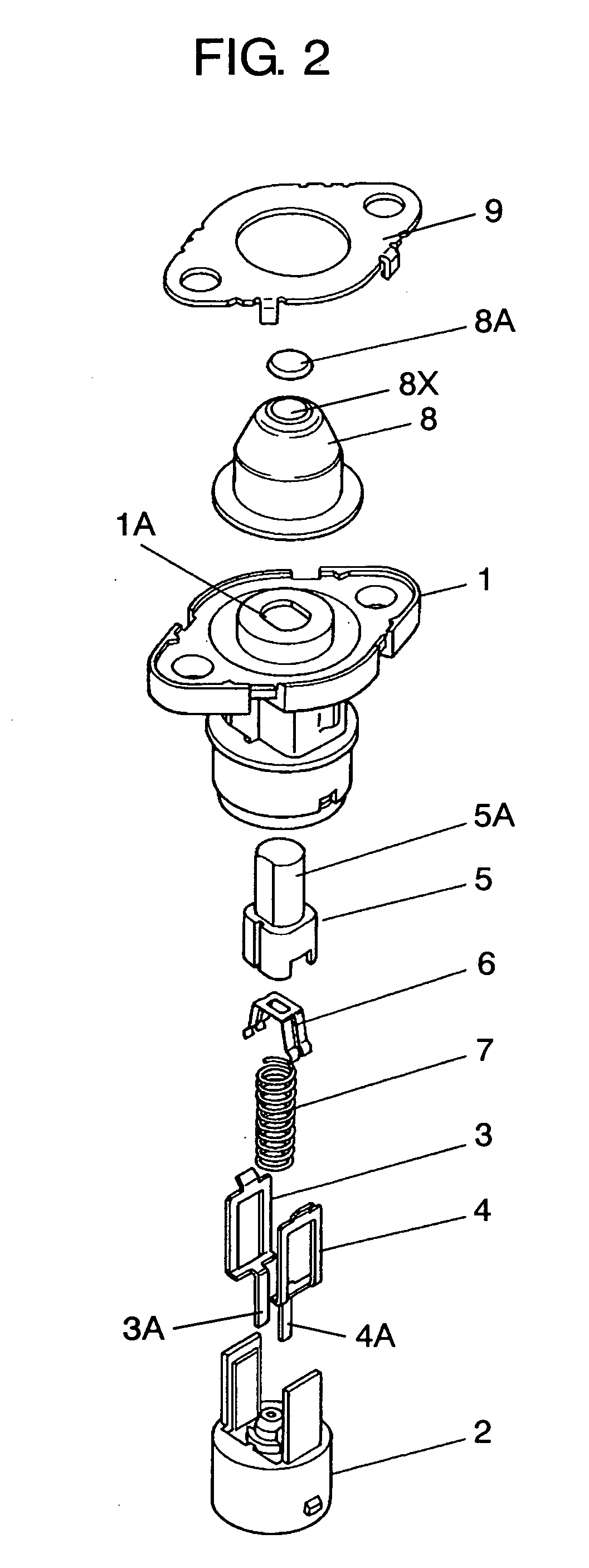
[0021]FIG. 1 is a sectional view of a vehicle switch in accordance with an exemplary embodiment of the present invention. FIG. 2 is an exploded perspective view thereof. Outer case 1 is substantially shaped like a cylinder and made of an insulating resin, such as polyacetal and polybutylene terephthalate. Through-hole 1A is formed through the top face of outer case 1. Inner case 2F is fitted and fixed into outer case 1. In this manner, outer case 1 and inner case 2 structure a case having through-hole 1A through one face. Additionally, fixed contacts (hereinafter referred to as contacts) 3 and 4 made of metal, such as copper alloy, are embedded in the right and left portions of the inner wall so that the contacts are opposed to each other.

[0022] Operating body 5 made of an insulating resin, such as polyacetal and nylon, is housed in inner case 2 vertically movable. Operating portion 5A at the top end of operating body 5 projects from through-hole 1A upwardly. In other words, operat...


PUM


Abstract

A vehicle switch includes a case having a through-hole through the top face thereof, an operating body, a switch contact, an elastic cover, and a sliding part. The top end of the operating body projects from the through-hole. The operating body is housed in the case vertically movable. The switch contact is brought into and out of electrical contact by the vertical movement of the operating body. The elastic cover covers the through-hole of the case and the top end of the operating body. The sliding part that has a smaller friction coefficient than that of the elastic cover is provided in the top portion of the elastic cover, and covers at least the rim of the top portion of the elastic cover, or protrudes from the top face of the top portion and has an arc-shaped curved surface in the outer periphery of the upper rim thereof.

Description

BACKGROUND OF THE INVENTION [0001] 1. Field of the Invention [0002] The present invention relates to switches for a vehicle (hereinafter referred to as vehicle switches) that are incorporated mainly in a vehicle and used to detect whether a door thereof is opened or closed. [0003] 2. Background Art [0004] It is widely applied to control turning on and off the lighting apparatuses in a vehicle cabin, by using a vehicle switch incorporated in the door part thereof according to opening and closing operation of the door. In many cases, such a vehicle switch is incorporated in a place exposed to water drops, such as rain, when the door is open; therefore, the vehicle switch is protected from water by a rubber cover or other parts. A description is provided of such a conventional vehicle switch in reference to FIGS. 6 to 8B. [0005]FIG. 6 is a sectional view of a conventional vehicle switch. FIG. 7 is an exploded perspective view thereof. Into outer case 31 that is made of an insulating re...

Claims


Application Information

Patent Timeline
IPC IPC(8): H01H13/04
CPCH01H3/62H01H13/06H01H2009/048H01H2011/0081
Inventor SHIROSHITA, MANABU
Owner PANASONIC CORP
Why Eureka
Try Eureka