Autonomous, back-packable computer-controlled breakaway unmanned aerial vehicle (UAV)

a computer-controlled, autonomous technology, applied in the field of unmanned aircraft, can solve the problems of affecting the data gathering mission, affecting the assembly process, and causing considerable damage to the airframe of the uav, and achieve the effect of rapid assembly

Inactive Publication Date: 2006-05-04
L 3 COMM CORP
View PDF10 Cites 172 Cited by
  • Summary
  • Abstract
  • Description
  • Claims
  • Application Information

AI Technical Summary

Benefits of technology

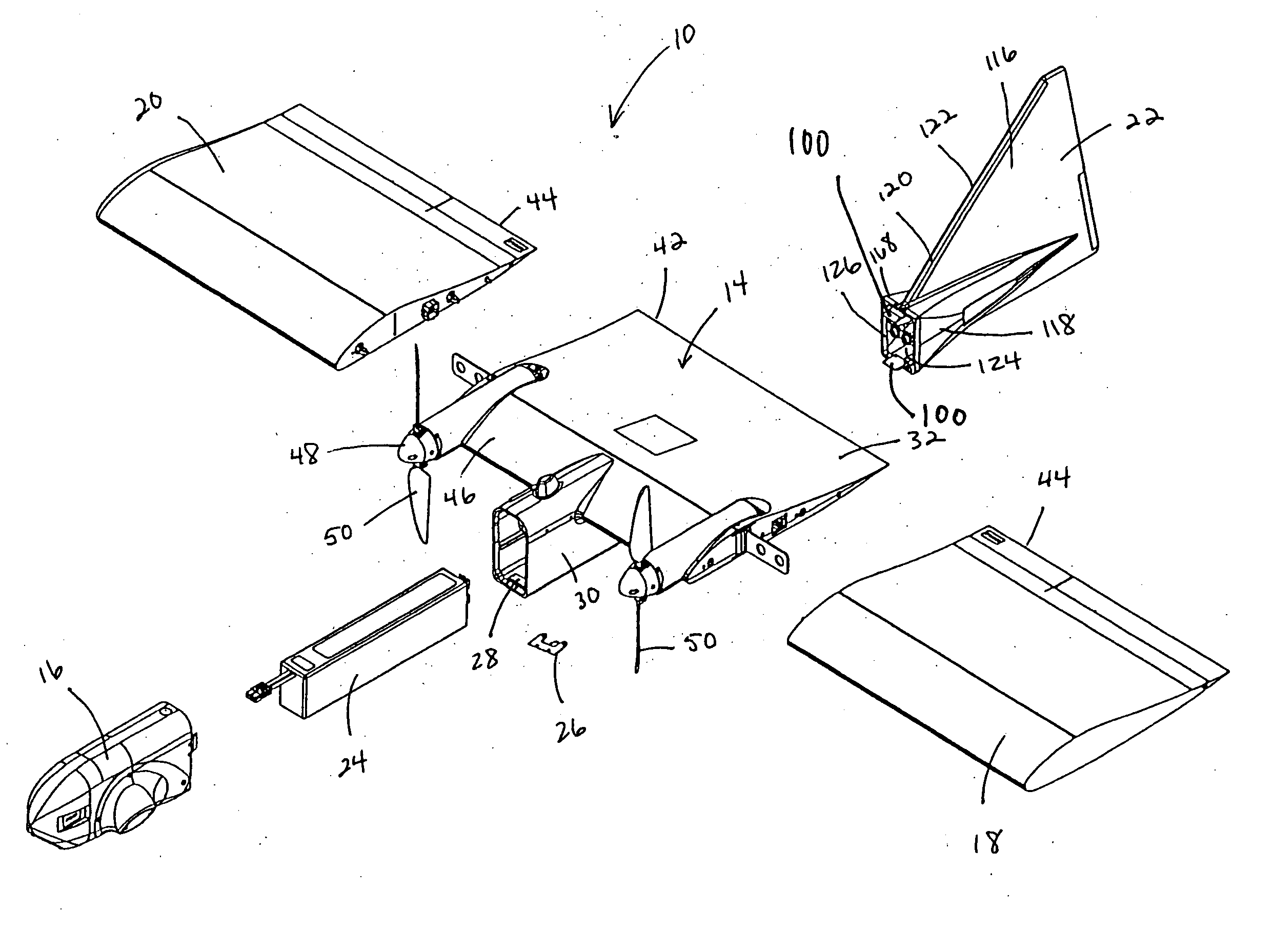
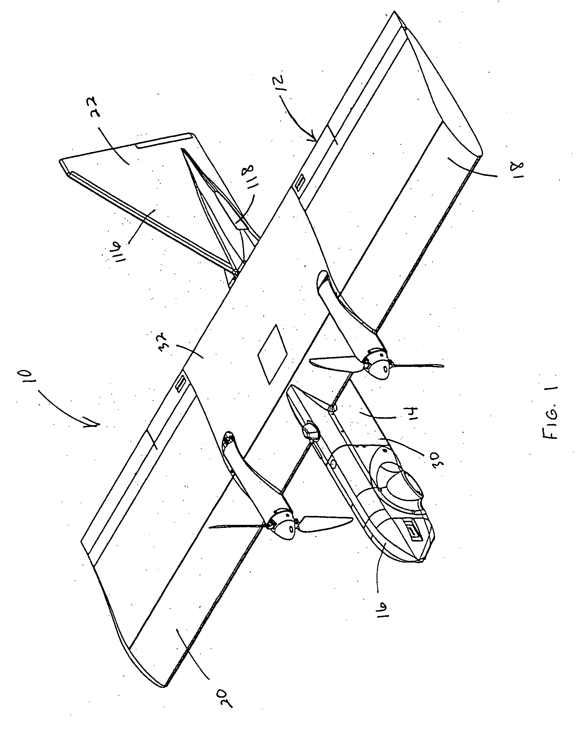
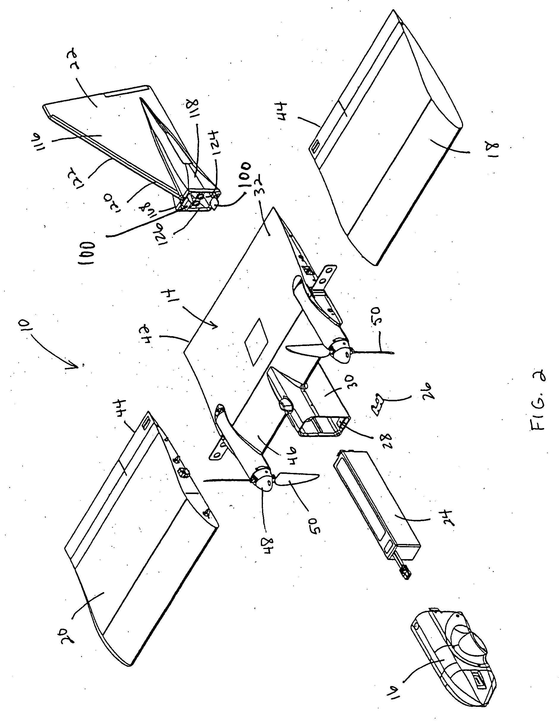
[0009] It is therefore an object of the present invention to provide an unmanned aerial vehicle (UAV) which overcomes the problems in prior art vehicles and meets the needs described above. Accordingly, the present invention is directed to a modular UAV having a

Problems solved by technology

With known UAV designs, the assembly process is often slowed due to the nature of the component connection elements which are often difficult to align and which can appear to be connected properly when in fact, the components are slightly out of alignment.
Once in flight, conventional UAV wing designs in which the servos controlling the elevons are mounted on the fuselage often cause the UAV to oscillate, resulting in instability that can negatively impact the data gathering mission.
Further difficulties often arise when the UAV returns upon c

Method used


Image

  • Autonomous, back-packable computer-controlled breakaway unmanned aerial vehicle (UAV)
  • Autonomous, back-packable computer-controlled breakaway unmanned aerial vehicle (UAV)
  • Autonomous, back-packable computer-controlled breakaway unmanned aerial vehicle (UAV)

Examples


first embodiment

[0096] as shown in FIGS. 23 and 24, the transport case, generally designated by the reference numeral 270, has a compartment area 272 that is partially filled with an impact absorbing insert 274 having specially sized cutouts 276 therein to accommodate the various components. This insert 274 may be a foam-type cushioning element or other comparable structure. Once the components (including preferably two nose cones 16) are inserted into their respective cutouts 276 with a friction fit, as shown in FIG. 24, the lid 278 may be closed and the case 270 easily carried in a backpack. The case itself may be provided with straps (not shown) to enable the user to place the case upon one's back for transport as a self-contained backpack. The outer shell of the case is preferably waterproof.

second embodiment

[0097] In the transport case illustrated in FIG. 25, the transport case, generally designated by the reference numeral 280, has a hard outer shell 282 with a body 284 and a hinged lid 286. The compartment area 288 within the body 284 is separated into a fuselage side 290 and a wing piece side 292 by a corrugated divider element 294 that further defines within itself a sleeve 296 for receipt of the stabilizer portion 116 of the tail section 22 when the latter is oriented as shown in FIG. 25.

[0098] The fuselage side 290 of the divided compartment 288 is provided with a foam-type cushioning insert 298 having specially formed nose cone cutouts 300 and fuselage cutout 302 therein to accommodate the fuselage and nose cones and hold the same with a friction fit. The wing piece side 292 of the divided compartment 288 is generally open, but is also preferably lined with a foam cushioning layer 304, and is sized to receive both wing pieces when the latter are juxtaposed as shown in FIG. 25. T...


PUM


Abstract

A modular unmanned aerial vehicle (UAV) having a fuselage, a nose cone, a left wing piece, a right wing piece, and a tail section. The tail section and nose cone each join to the fuselage through mating bulkhead structures that provide quick connection capability while being readily separated so as to enable the UAV to break apart at these connection points and thereby absorb or dissipate impact upon landing. The UAV is capable of rapid assembly in the field for two-man launch and data retrieval, as well as quick disassembly into these five component parts for transport and storage in a highly compact transport case that can be carried as a backpack.

Description

BACKGROUND OF THE INVENTION [0001] 1. Field of the Invention [0002] The present invention relates generally to unmanned aircraft and, more particularly to a hand-launchable unmanned aerial vehicle (UAV) carrying sensor instrumentation for terrain surveillance, in which the components of the UAV are easily assembled in the field, can absorb landing shocks, and can be disassembled so as to fit in a small size package. [0003] 2. Description of the Related Art [0004] There is a need for a small size unmanned aerial vehicle (UAV) which is able to collect data from a sensor such as a television camera carried on board the UAV and transmit the collected data to be received by a ground receiver, as for example at the point of launch. [0005] Such a UAV must be capable of being disassembled, transported in a small size container to the point of launch, then quickly reassembled and launched, for data retrieval. With known UAV designs, the assembly process is often slowed due to the nature of t...

Claims


Application Information

Patent Timeline
IPC IPC(8): B64C27/22
CPCA45C5/00B64C2201/203B64C1/00B64C1/30B64C39/024B64C2201/021B64C2201/042B64C2201/084B64C2201/102B64C2201/126B64C2201/127B64C2201/141B64C2201/165B64C2201/201B64C2201/187A45C13/02B64U10/25B64U70/70B64U2201/10B64U50/19B64U50/13B64U70/60B64U80/70B64U80/60B64U2101/31B64U20/40B64U30/14B64U2101/64B64U30/12B64U2101/00B64U2101/30
Inventor CHIU, TIEN SENGWILLMOTT, JAY
Owner L 3 COMM CORP
Why Eureka
Try Eureka