

Exciter ring for a brake rotor
a technology of exciter ring and brake rotor, which is applied in the direction of braking system, brake disc, brake disc, etc., can solve the problems of reducing traction, causing the wheel to “lock up” and stop rotating, and causing the ability to steer the vehicle, truck or tractor-trailer to become unstable,
- Summary
- Abstract
- Description
- Claims
- Application Information
AI Technical Summary
Problems solved by technology
Method used
Image

Examples
Embodiment Construction
[0002] Anti-lock braking systems (“ABS”) are used to increase traction and control of a vehicle under difficult braking conditions. On slippery surfaces, braking can cause the wheel to “lock up” and stop rotating. As a result, the portion of the wheel in contact with the road simply slides relative to the surface, which severely reduces traction and the ability to steer the vehicle. The loss (reduction) of traction causes the truck or tractor-trailer to become unstable and directional control becomes difficult. This problem is of particular concern for heavy commercial vehicles, such as tractor-trailers, where the loss of control can cause the vehicle to jack-knife.
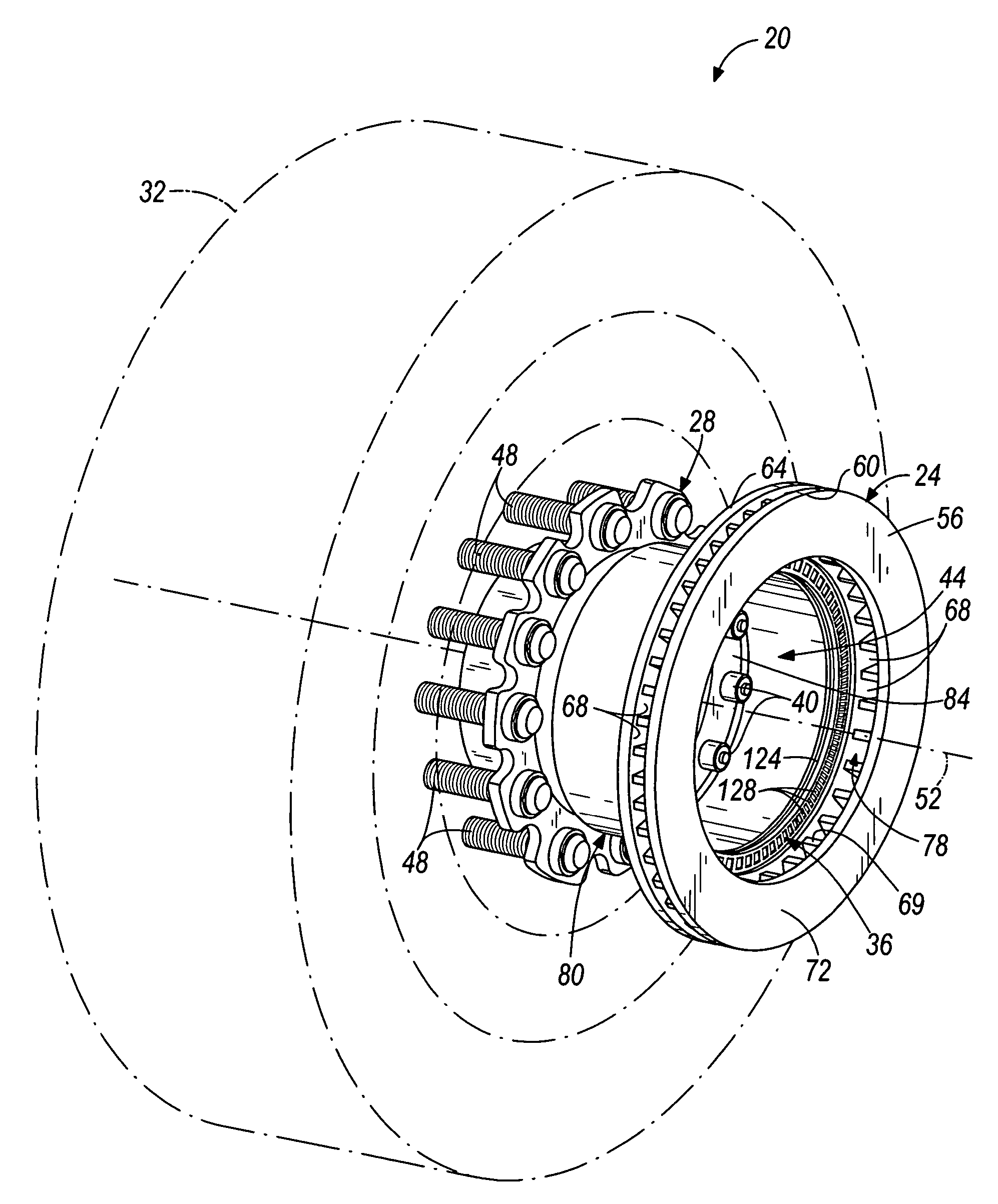
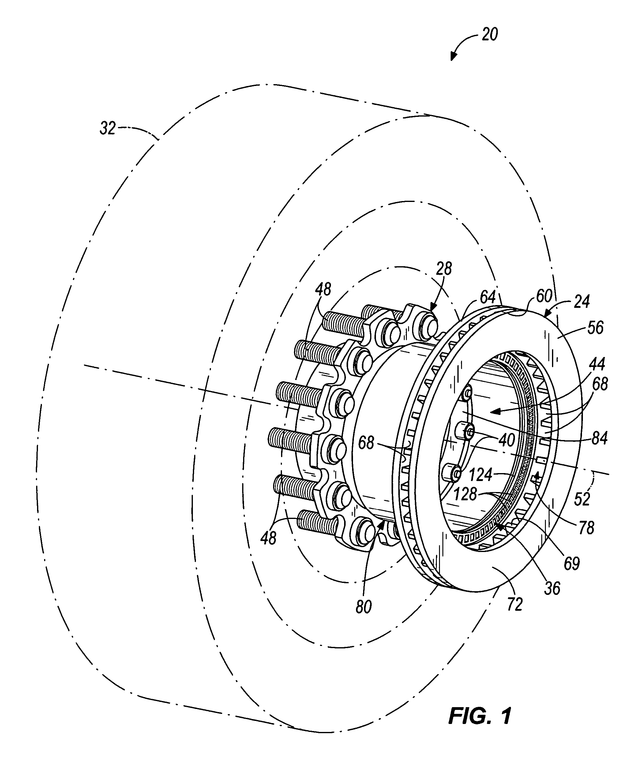
[0003] ABS systems prevent wheel lock up by rapidly releasing and reapplying pressure to the brakes, to permit the skidding wheel to regain traction and steering. ABS systems typically comprise a speed sensor positioned adjacent to four or more wheels of the vehicle. Each speed sensor is connected to a controller that mo...
PUM
 Abstract
Description
Claims
Application Information