This helps you quickly interpret patents by identifying the three key elements:
Problems solved by technology
Method used
Benefits of technology
Benefits of technology
[0024] Therefore, the present invention has been made in view of the above problems, and it is an object of the present invention to provide a linear compressor showing a simplified structure and assembling process.
[0025] It is another object of the present invention to provide a linear compressor showing an easy tolerance control of a magnet.
[0036] According to the linear compressor of the present invention configured as stated above, since the inner core is mounted to linearly reciprocate simultaneously with the piston, and the magnet holder, having the magnet mounted therein, is mounted on the inner core, the structure of the compressor can be simplified, resulting in a reduced number of parts and low manufacturing costs.
[0037] Further, according to the present invention, the inner core includes the first inner core having the rear holding protrusion and the second inner core coupled to a front side of the first inner core and having a front holding protrusion, so that the magnet holder can be stably mounted on the inner core as front and rear ends thereof are caught by the front and rear holding protrusions of the first and second inner cores. This eliminates the need of separate adhesive for attaching the magnet holder to the inner core, and can prevent deformation of coupling regions of the inner core and the magnet holder, enabling easy tolerance control of the magnet.
[0038] Furthermore, as a result of forming the protrusion at one of the first and second inner cores and the recess at the other one of the first and second inner cores, the first and second inner cores can be easily coupled to each other.
Problems solved by technology
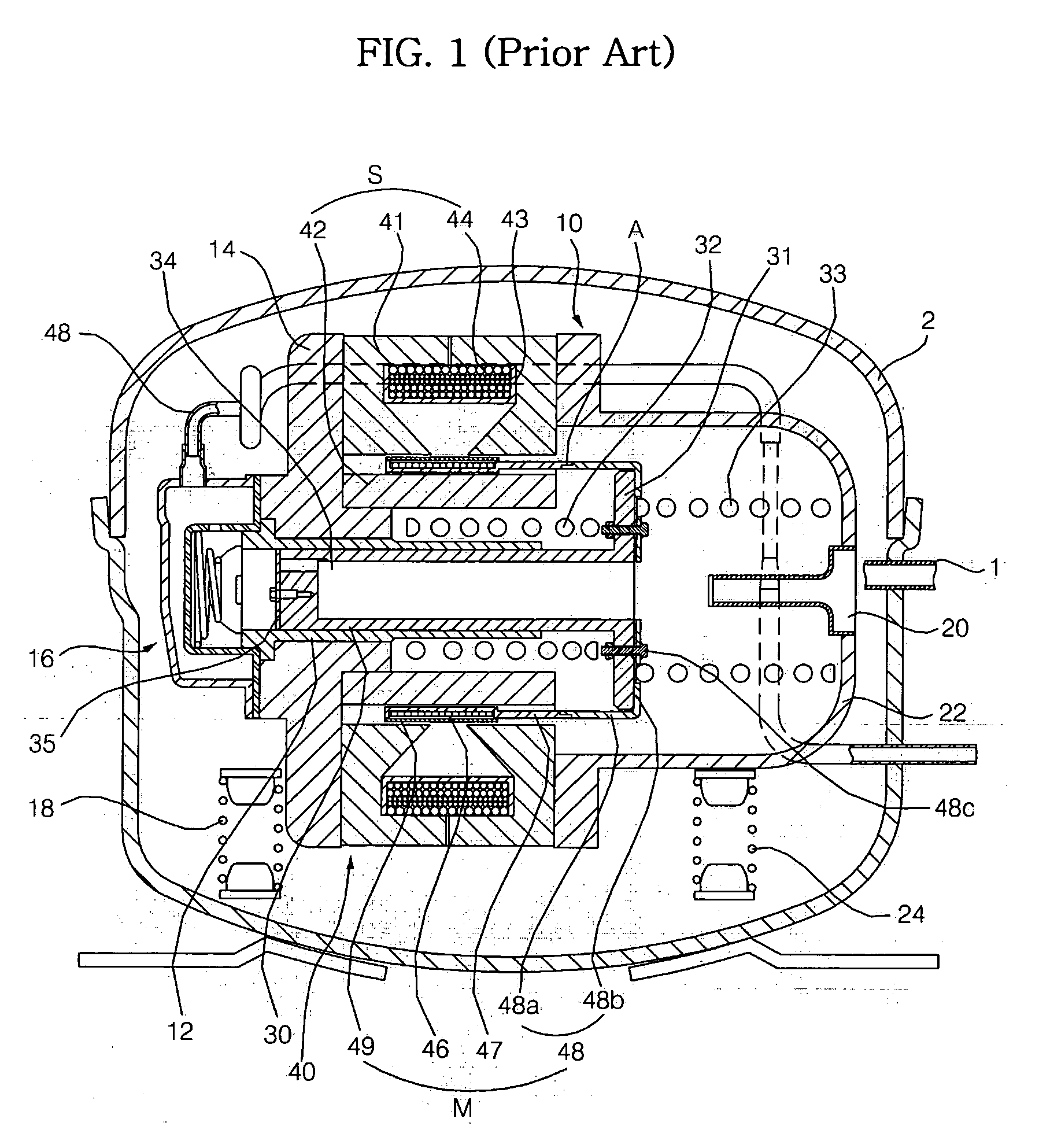
Composing the mover M of the linear motor 40 with the magnet 46, carbon frame 47, top plate 48, and carbon winding 49, however, excessively increases the number of parts, and complicates the assembling process thereof.
Thus, the conventional linear compressor suffers from a difficulty in tolerance control.
Also, the conventional linear compressor has a problem in that an attachment region between the carbon frame 47 and the top plate 48 is easily deformed.
This worsens a difficulty in accurate tolerance control of the compressor.
Method used
Image
Click on the blue label to locate the original text in one second.
Reading with bidirectional positioning of images and text.
Examples
first embodiment
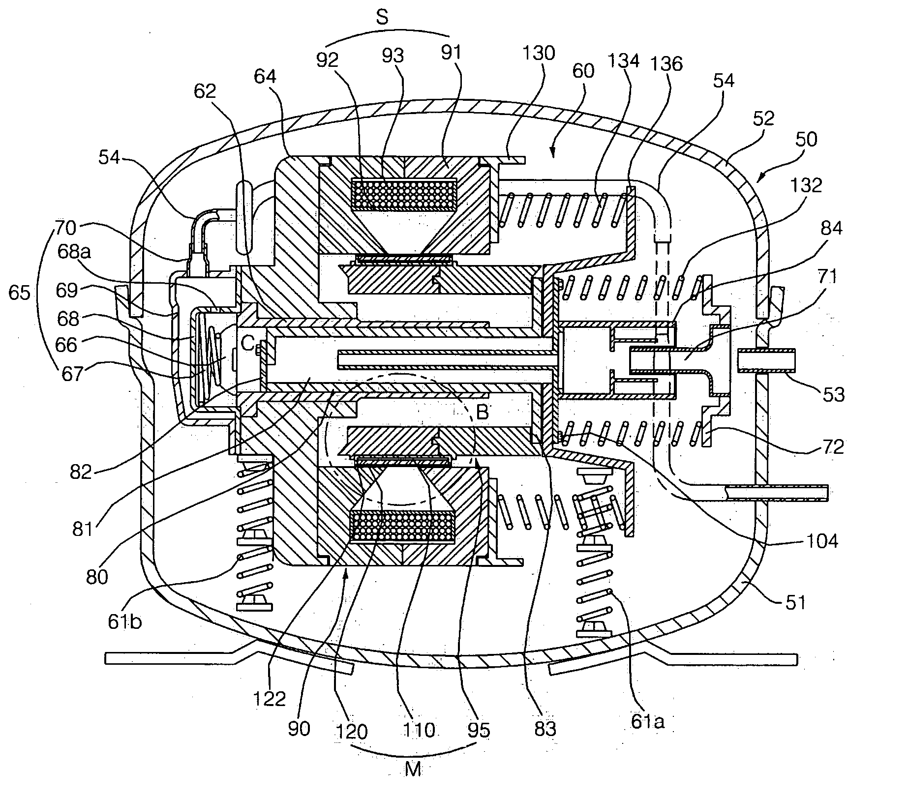
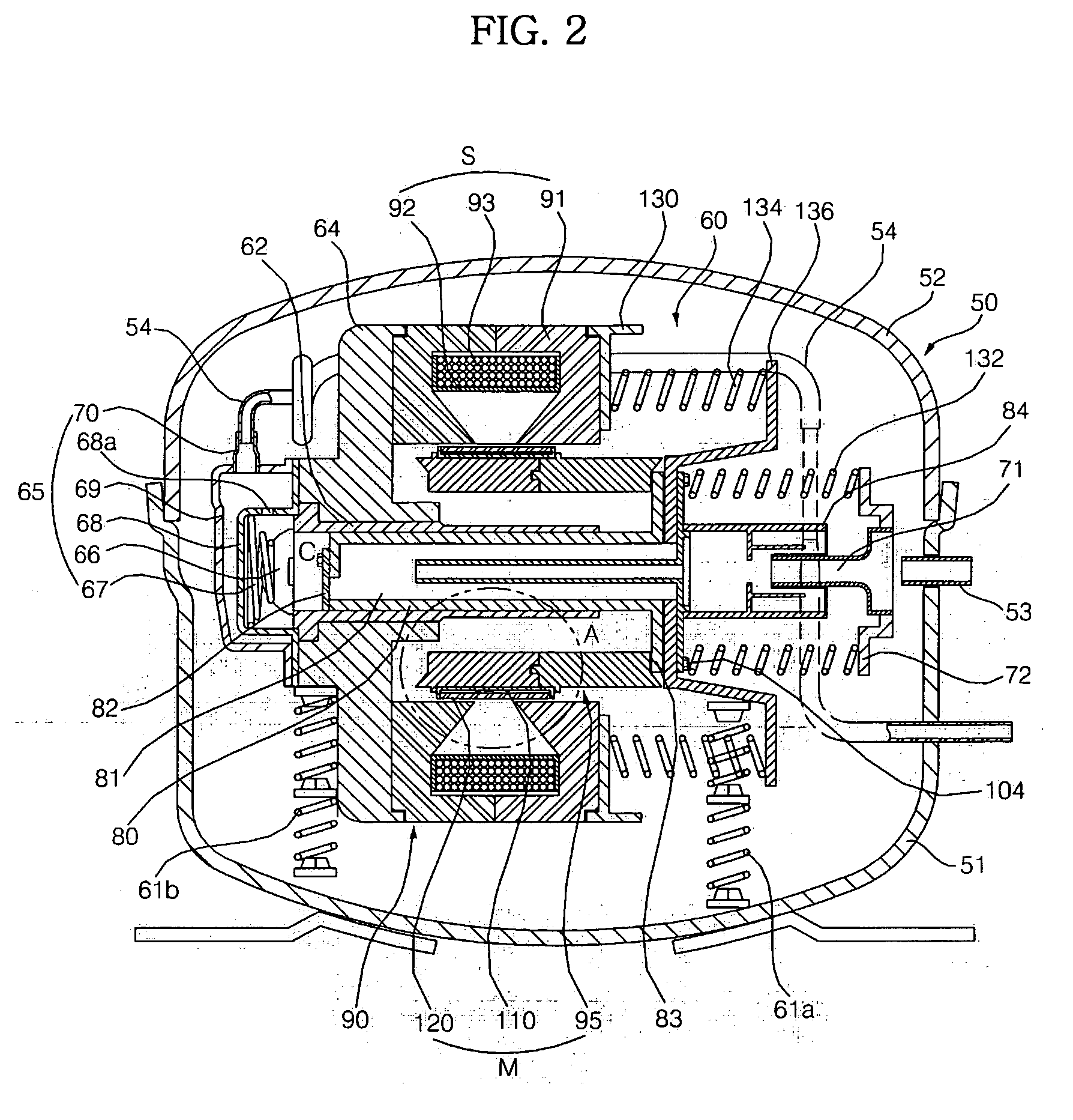
[0049]FIG. 2 is a sectional view illustrating the interior configuration of a linear compressor according to the present invention.
[0050] As shown in FIG. 2, the linear compressor according to the present embodiment includes a hermetic shell 50, and a linear compression unit 60 mounted in the hermetic shell 50.
[0051] The hermetic shell 50 includes a lower shell 51, and an upper shell 52 configured to cover an upper side of the lower shell 51. In a coupled state thereof, both the lower and upper shells 51 and 52 define a hermetic space therein.
[0052] A suction pipe 53 is penetrated through the hermetic shell 50 to introduce fluid, such as refrigerant gas (hereinafter referred to as “fluid”), into the hermetic shell 50. A loop pipe 54 is also penetrated through the hermetic shell 50 to guide the compressed fluid from the linear compression unit 60 to the outside of the hermetic shell 50.
[0053] A rear portion of the linear compression unit 60 is supported by a first damper 61a that ...
second embodiment
[0094]FIG. 5 is a sectional view illustrating the interior configuration of a linear compressor according to the present invention. FIG. 6 is an enlarged sectional view of the circle B shown in FIG. 5.
[0095] As shown in FIGS. 5 and 6, according to the linear compressor of the present embodiment, a carbon winding 122 is wound on the magnet 120 mounted in the magnet holder 110. The other configuration and operation of the present embodiment, except for the carbon winding 122, is identical to the first embodiment. Thus, the same reference numerals will be used in the present embodiment to refer to the same or like parts, and a detailed description will be omitted.
third embodiment
[0096]FIG. 7 is a sectional view illustrating the interior configuration of a linear compressor according to the present invention. FIG. 8 is an enlarged sectional view of the circle D shown in FIG. 7.
[0097] As shown in FIGS. 7 and 8, the linear compressor according to the present embodiment includes an inner core holder 124 mounted to the piston 80 to support the inner core 95 mounted thereon. Differently from the first embodiment of the present invention wherein the inner core 95 is directly affixed to the piston 80, the inner core 95 of the present embodiment is connected to the piston 80 via the inner core holder 124.
[0098] The other configuration and operation of the present embodiment, except for the inner core holder 124, is identical to the first or second embodiment. Thus, the same reference numerals will be used in the present embodiment to refer to the same or like parts, and a detailed description will be omitted.
[0099] The inner core holder 124 is comprised of a first...
PUM
Abstract
Disclosed herein is linear compressor. The linear compressor comprises a cylinder, a piston disposed to linearly reciprocate into the cylinder, and a linear motor provided to linearly reciprocate the piston. The linear motor includes an outer core, a bobbin mounted in the outer core, a coil wound on the bobbin, an inner core spaced apart from the outer core to define a gap therebetween, the inner core being mounted to linearly reciprocate simultaneously with the piston, a magnet holder mounted on the inner core, and a magnet mounted in the magnet holder. The linear compressor has a simplified structure, resulting in a reduced number of parts and low manufacturing costs.
Description
BACKGROUND OF THE INVENTION [0001] 1. Field of the Invention [0002] The present invention relates to a linear compressor to compress refrigerant gas, etc., and, more particularly, to a linear compressor in which an inner core is mounted to reciprocate simultaneously with a piston, and a magnet holder, having a magnet mounted therein, is mounted on the inner core. [0003] 2. Description of the Related Art [0004] Generally, a linear compressor is configured to suction fluid, such as refrigerant gas (hereinafter, referred to as “fluid”), into a cylinder and compress the fluid by linearly reciprocating a piston inside the cylinder using a linear driving force of a linear motor to thereby discharge the fluid in a compressed state. [0005]FIG. 1 is a sectional view illustrating the interior configuration of a conventional linear compressor. [0006] As shown in FIG. 1, the conventional linear compressor includes a hermetic shell 2 having an inlet port 1 for the introduction of fluid from the ...
Claims
Application Information
Patent Timeline
Application Date:The date an application was filed.
Publication Date:The date a patent or application was officially published.
First Publication Date:The earliest publication date of a patent with the same application number.
Issue Date:Publication date of the patent grant document.
PCT Entry Date:The Entry date of PCT National Phase.
Estimated Expiry Date:The statutory expiry date of a patent right according to the Patent Law, and it is the longest term of protection that the patent right can achieve without the termination of the patent right due to other reasons(Term extension factor has been taken into account ).
Invalid Date:Actual expiry date is based on effective date or publication date of legal transaction data of invalid patent.

