Gas discharge apparatus and plasma display panel

Inactive Publication Date: 2006-05-04
LG ELECTRONICS INC
View PDF0 Cites 0 Cited by
  • Summary
  • Abstract
  • Description
  • Claims
  • Application Information

AI Technical Summary

Benefits of technology

[0023] Accordingly, it is an object of the present invention to provide a gas discharge app

Problems solved by technology

However, the high density Xe PDP or the long gap PDP has disadvantage that a discharge firing voltage or a discharge voltage becomes higher in comparison with the low density Xe or show gap PDP.
Further, in the high density Xe PDP or the long gap PDP, the discharge voltage where the discharge starts becomes higher, thus there is a problem th

Method used


Image

  • Gas discharge apparatus and plasma display panel
  • Gas discharge apparatus and plasma display panel
  • Gas discharge apparatus and plasma display panel

Examples


Embodiment Construction

[0062] Reference will now be made in detail to the preferred embodiments of the present invention, examples of which are illustrated in the accompanying drawings.

[0063] Hereinafter, the preferred embodiments of the present invention will be described in detail with reference to FIGS. 4 to 10.

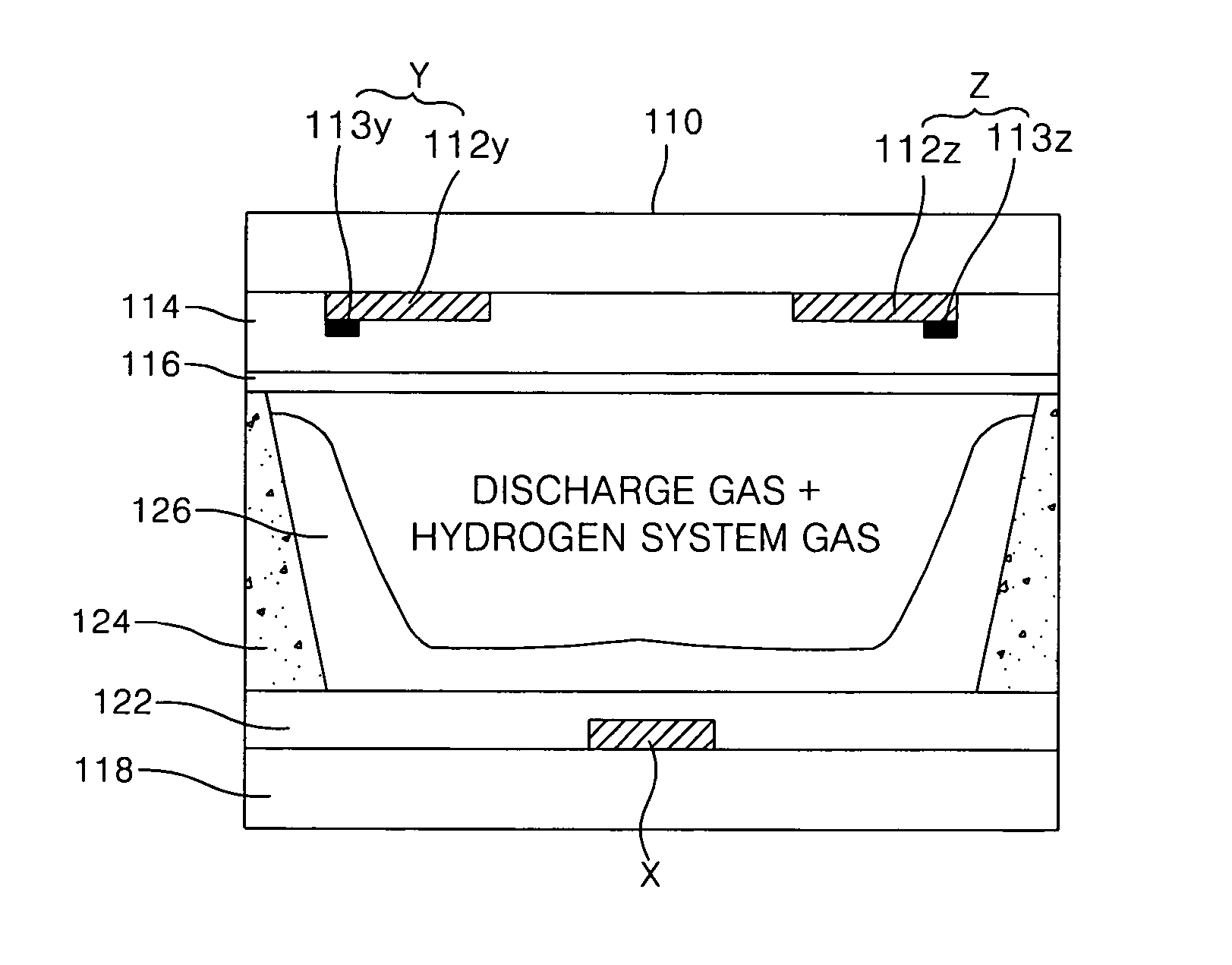
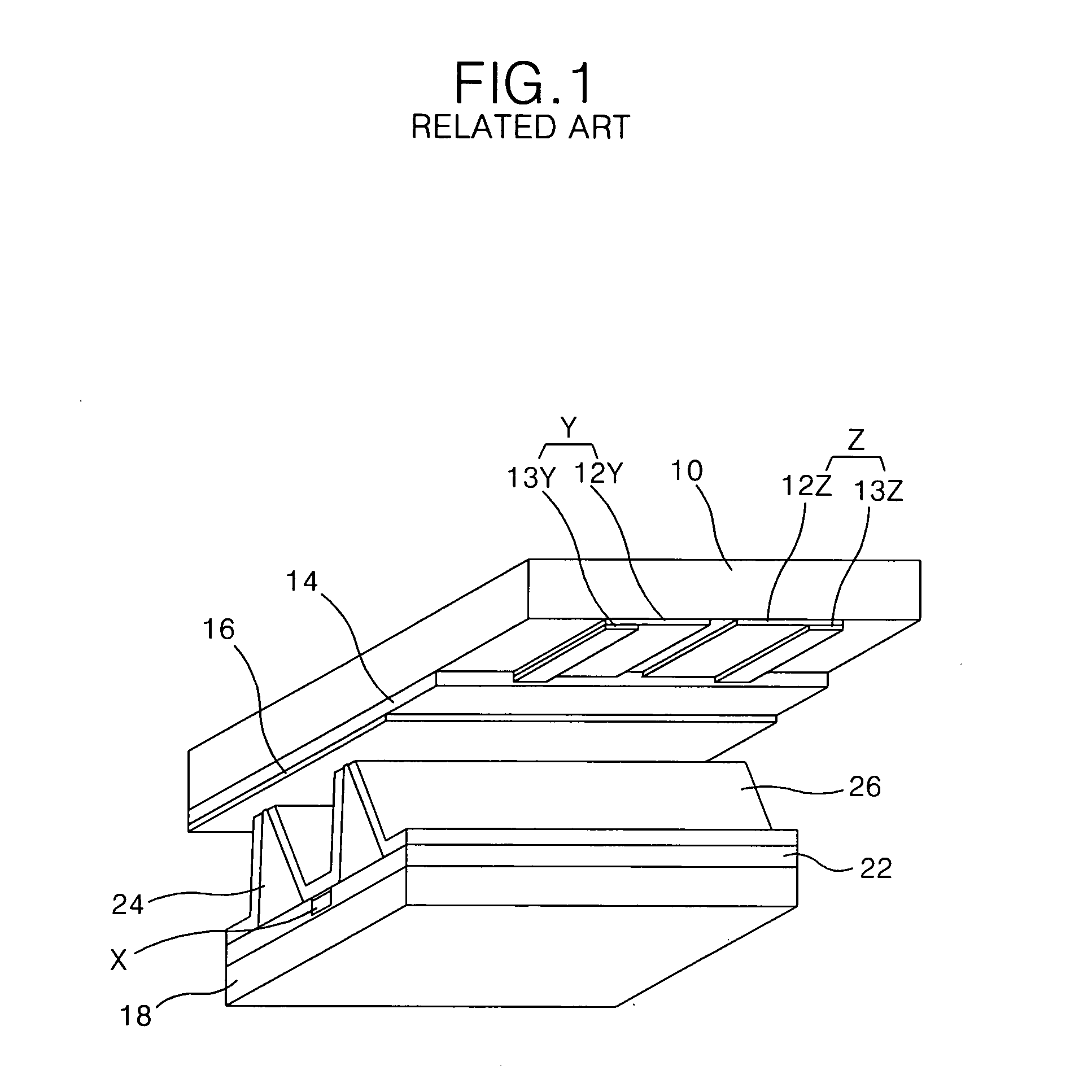
[0064]FIG. 4 is a sectional diagram representing a discharge cell of a PDP according to an embodiment of the present invention. In FIG. 4, in order that the structure of all the electrodes is clearly shown, a lower substrate of the PDP rotates in relation to an upper substrate of the PDP by 90°.

[0065] Referring to FIG. 4, the PDP according to the embodiment of the present invention includes a scan electrode Y and a sustain electrode Z formed on an upper substrate 110, and an address electrode X formed on a lower substrate 118. Each of the scan electrode Y and the sustain electrode Z includes transparent electrodes 112Y, 112Z and metal bus electrodes 113Y, 113Z of which each has a narrower lin...


PUM


Abstract

There is disclosed a gas discharge apparatus that is adaptive for reducing a discharge voltage as well as increasing its brightness and luminescence efficiency. In a gas discharge apparatus according to an embodiment of the present invention, a discharge gas injected into the discharge space includes a hydrogen group isotope gas in a mixture ratio of 0.01%˜2.0%.

Description

[0001] This application claims the benefit of the Korean Patent Application Nos. P2004-87528 and P2004-111509 filed on Oct. 29, 2004, and on Dec. 23, 2004 which are hereby incorporated by reference. BACKGROUND OF THE INVENTION [0002] 1. Field of the Invention [0003] The present invention relates to a gas discharge apparatus, and more particularly to a gas discharge apparatus and a plasma display panel that is adaptive for reducing a discharge voltage as well as increasing its brightness and luminescence efficiency. [0004] 2. Description of the Related Art [0005] Generally, a gas discharge apparatus is made in a tube or panel shape to be used as a lighting light source. Recently, a plasma display panel (hereinafter, referred to as “PDP”), which displays a picture by use of gas discharge principle, is put on the market. [0006] The PDP has attracted attention as a large sized flat panel display, and it makes a phosphorus emit light by an ultraviolet ray of 147 nm which is generated upo...

Claims


Application Information

Patent Timeline
IPC IPC(8): H01J17/49H01J11/24H01J11/50
CPCH01J11/12H01J11/50
Inventor AHN, SUNG YONG
Owner LG ELECTRONICS INC
Why Eureka
Try Eureka