Lithographic apparatus and device manufacturing method

a technology of lithographic apparatus and manufacturing method, which is applied in the direction of optical devices, instruments, photomechanical apparatus, etc., can solve the problems of non-uniform cd distribution across the target portion, non-uniform transmission or reflectance of the mask, and uneven cd across the target portion

Active Publication Date: 2006-05-04
ASML NETHERLANDS BV
View PDF4 Cites 16 Cited by
  • Summary
  • Abstract
  • Description
  • Claims
  • Application Information

AI Technical Summary

Benefits of technology

[0012] It is thus unnecessary to expose a test wafer to measure the uniformity of the projection beam and the mask. This leads to savings in the time and complexity involved in measuring the uniformity. The radiation dose applied to the substrate can be adjusted to compensate for the measured non-uniformity in the projection beam and mask.

Problems solved by technology

If the transmission or reflectance across the mask is not uniform, then the CD across the target portion will not be uniform.
Non-uniformity of the transmission or reflectance of the mask may be caused by non-uniformity in the transmission or reflectance of the mask substrate or a variation in the size of features on the mask, or a combination of both.
Furthermore, there may be variations in the intensity of the projection beam across the target portion, and this will also lead to a non-uniform CD distribution across the target portion.
However, this does not take into account the variations introduced by the mask.
It is not practical simply to remove a mask from a reflective system, although a production mask can be replaced by a “blank” mask (i.e. a mask without a pattern) to reflect the beam towards the projection system in an effort to determine the non-uniformity of the projection beam.
The problem with this approach is that the reflection coefficient uniformity of a blank mask is generally not the same as that of a production mask, so a correction based on the uniformity of a blank mask will be suboptimal for the production mask.
However, this procedure involves a long cycle time and generally requires off-line tooling and related data logistics.

Method used


Image

  • Lithographic apparatus and device manufacturing method
  • Lithographic apparatus and device manufacturing method
  • Lithographic apparatus and device manufacturing method

Examples


Embodiment Construction

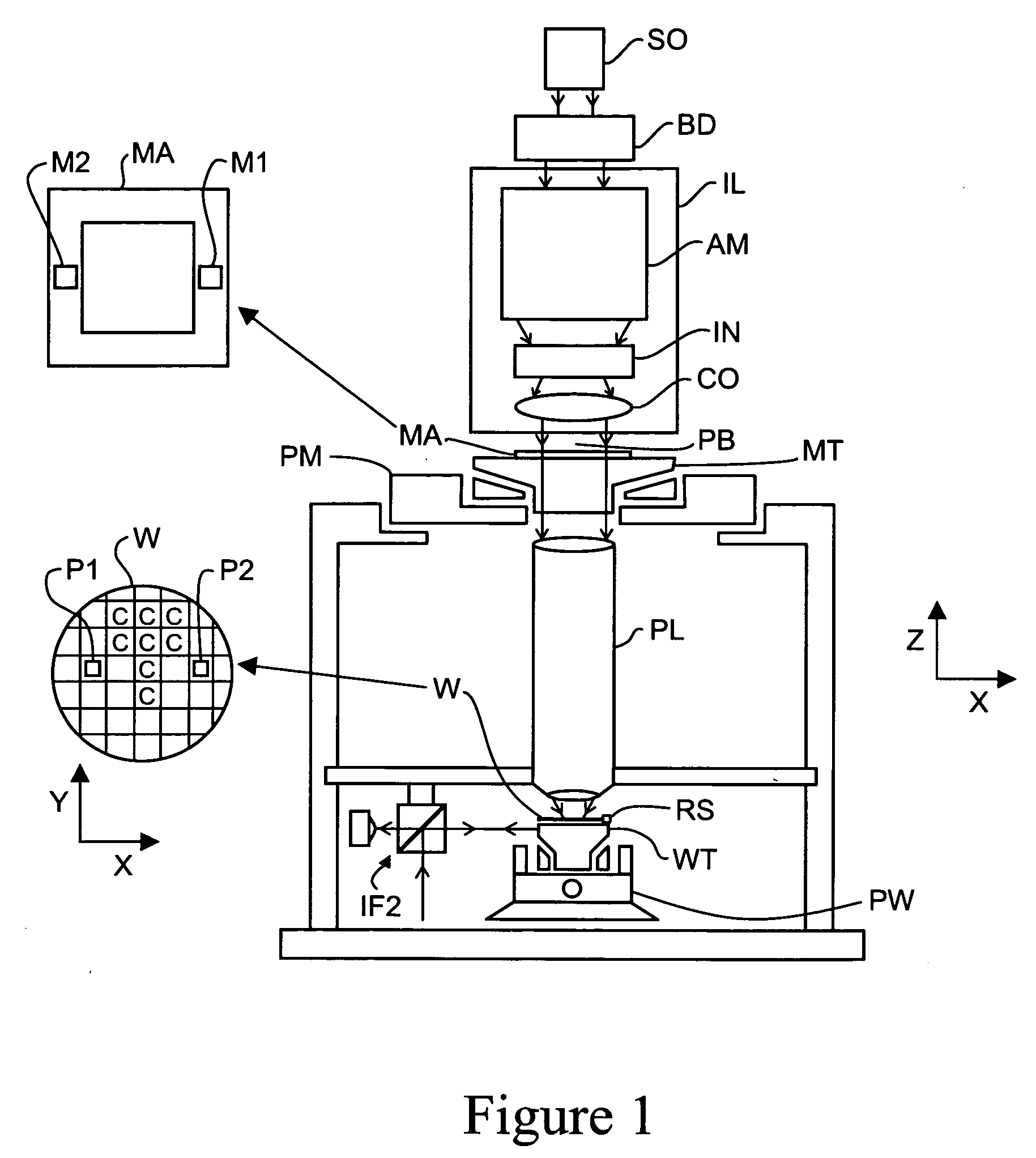
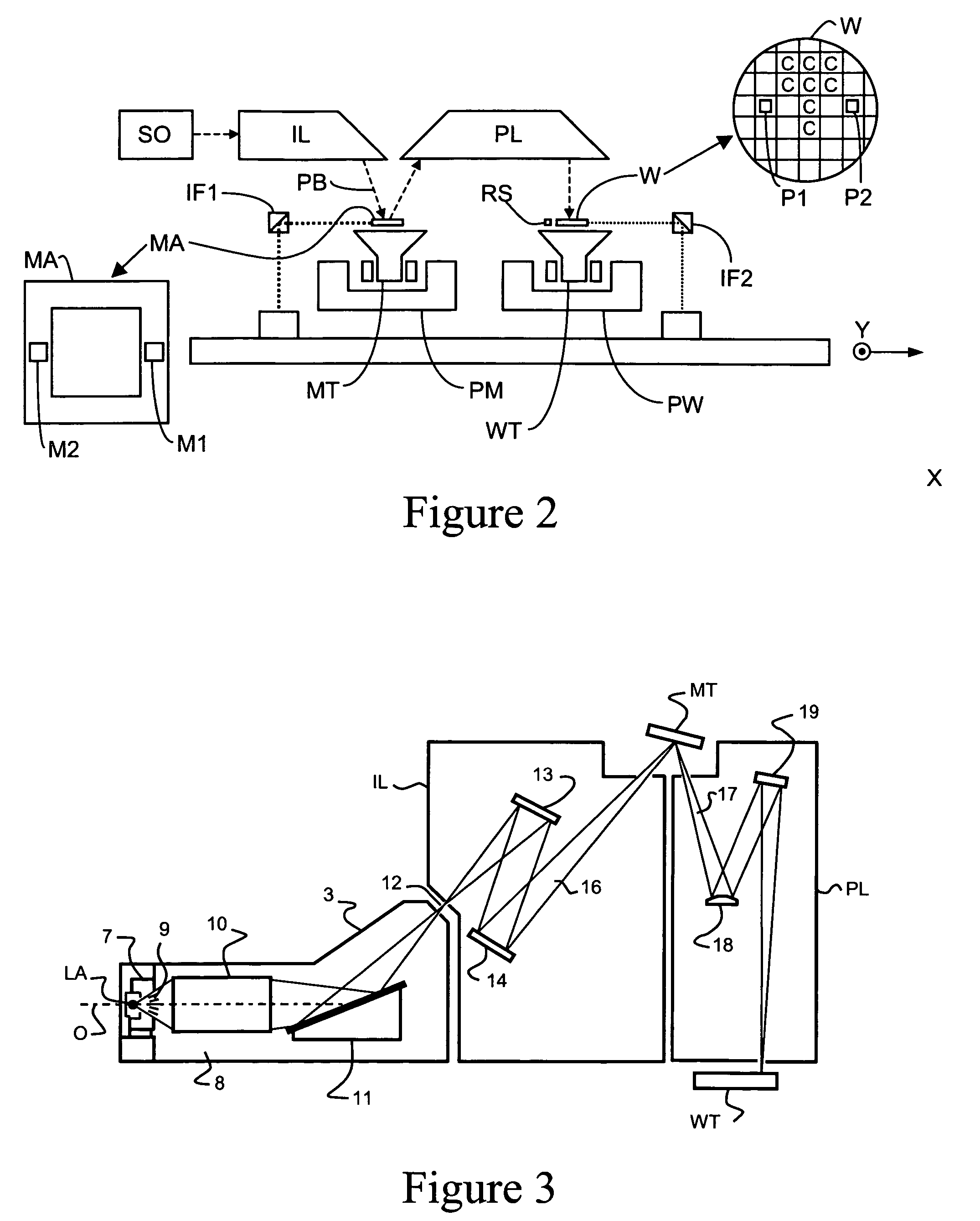
[0048]FIGS. 1 and 2 schematically depict two examples of a lithographic apparatus. In each case the apparatus comprises: [0049] an illumination system (illuminator) IL for providing a projection beam PB of radiation (e.g. UV radiation). [0050] a first support structure (e.g. a mask table) MT for supporting patterning devices (e.g. a mask) MA and connected to first positioner PM for accurately positioning the patterning device with respect to item PL; [0051] a substrate table (e.g. a wafer table) WT for holding a substrate (e.g. a resist-coated wafer) W and connected to a second positioner PW for accurately positioning the substrate with respect to item PL; and [0052] a projection system (e.g. a refractive or reflective projection lens) PL for imaging a pattern imparted to the projection beam PB by patterning device MA onto a target portion C (e.g. comprising one or more dies) of the substrate W.

[0053] As depicted in FIG. 1, the apparatus is of a transmissive type (i.e. employing a ...


PUM


Abstract

A lithographic apparatus comprises an illumination system for providing a projection beam of radiation, a support structure for supporting patterning device, the patterning device serving to transmit or reflect radiation in the projection beam and impart the projection beam with a pattern in its cross-section, a substrate table for holding a substrate, and a projection system for projecting the patterned beam onto a target portion of the substrate. A sensor is provided for measuring the spatial intensity distribution of the projection beam at the substrate. The spatial distribution of transmission or reflectance of the patterning device, together with the distribution of the projection beam incident on the patterning device, may be determined from the measured intensity distribution. By comparing the transmission or reflectance from regions having identical patterns the overall (macroscopic) distribution of the transmission or reflectance of the patterning device can be determined.

Description

FIELD OF THE INVENTION [0001] The present invention relates to a lithographic apparatus and a device manufacturing method. In particular, the invention relates to a method of measuring the uniformity of transmission or reflection of a production mask. BACKGROUND TO THE INVENTION [0002] A lithographic apparatus is a machine that applies a desired pattern onto a target portion of a substrate. Lithographic apparatus can be used, for example, in the manufacture of integrated circuits (ICs). In that instance, a patterning device, which is alternatively referred to as a mask or a reticle, may be used to generate a circuit pattern corresponding to an individual layer of the IC, and this pattern can be imaged onto a target portion (e.g. comprising part of, one or several dies) on a substrate (e.g. a silicon wafer) that has a layer of radiation-sensitive material (resist). In general, a single substrate will contain a network of adjacent target portions that are successively exposed. Lithogr...

Claims


Application Information

Patent Timeline
Patent Type & Authority Applications(United States)
IPC IPC(8): G03B27/54
CPCG03F7/70558G03F7/70666G03F7/70941
Inventor LAAN, HANS VAN DERMICKAN, UWEEURLINGS, MARKUS FRANCISCUS ANTONIUSVAN SCHOOT, JAN BERNARD PLECHELMUS
Owner ASML NETHERLANDS BV
Why Eureka
Try Eureka