
Actively-illuminating optical sensing system for an automobile

an active illumination and optical sensing technology, applied in the direction of distance measurement, pedestrian/occupant safety arrangement, instruments, etc., can solve the problems of affecting the ability of an affecting the ability of the active illumination optical sensing system to accurately and reproducibly perform its functions, and affecting the detection or sensing of light originating from the emitter. , the interference of ambient light with the detection or sensing of light is reduced

Inactive Publication Date: 2006-05-04
DELPHI TECH INC
View PDF5 Cites 22 Cited by
  • Summary
  • Abstract
  • Description
  • Claims
  • Application Information

AI Technical Summary

Benefits of technology

[0019] An advantage of the present invention is that the interference of ambient light with the detection or sensing of light originating from the emitter is reduced.
[0020] Another advantage is that inexpensive silicon-based light detectors may be used.
[0021] Yet another advantage is that the baseline ambient light received by the detector may be measured and distinguished from the light that originates from the emitter.
[0022] It is understood that although the specific embodiments presented in this document refer to occupants of automobiles, identical systems may be of advantage in other vehicular systems, including trucks, busses and other forms of transportation in which it is desirable to identify the state of occupants.
[0023] Similarly, advantageous use may be made of these concepts for other optical emitter / detector systems that may operate in the presence of large variations in ambient illumination.

Problems solved by technology

The performance of the optical sensor tends to be limited by these variations in the level of ambient light.
All of these sources, referred to herein as ambient light sources, may adversely affect the ability of an actively (self) illuminated optical sensing system to accurately and reproducibly perform its functions.
However, with no filtering, the light from the emitter may often be overwhelmed by high levels of ambient light.
Consequently, the optical system may not be able to discriminate between light emitted by the system and light originating from ambient sources.
The consequences of this upon the performance of the overall sensing are serious.
Consequently, known optical sensing systems may respond in a non-optimum manner to variations in ambient lighting, reducing the utility of such systems.

Method used


Image

  • Actively-illuminating optical sensing system for an automobile
  • Actively-illuminating optical sensing system for an automobile
  • Actively-illuminating optical sensing system for an automobile

Examples


Embodiment Construction

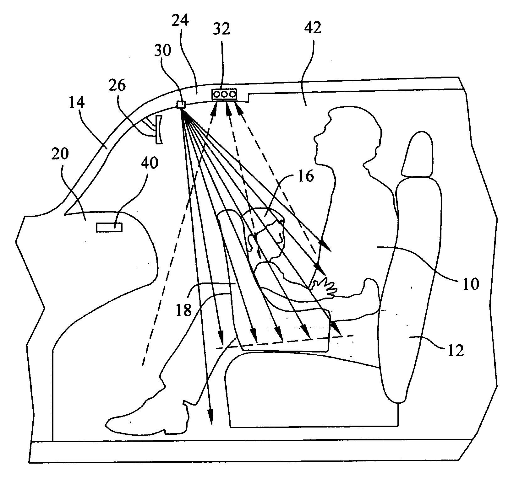
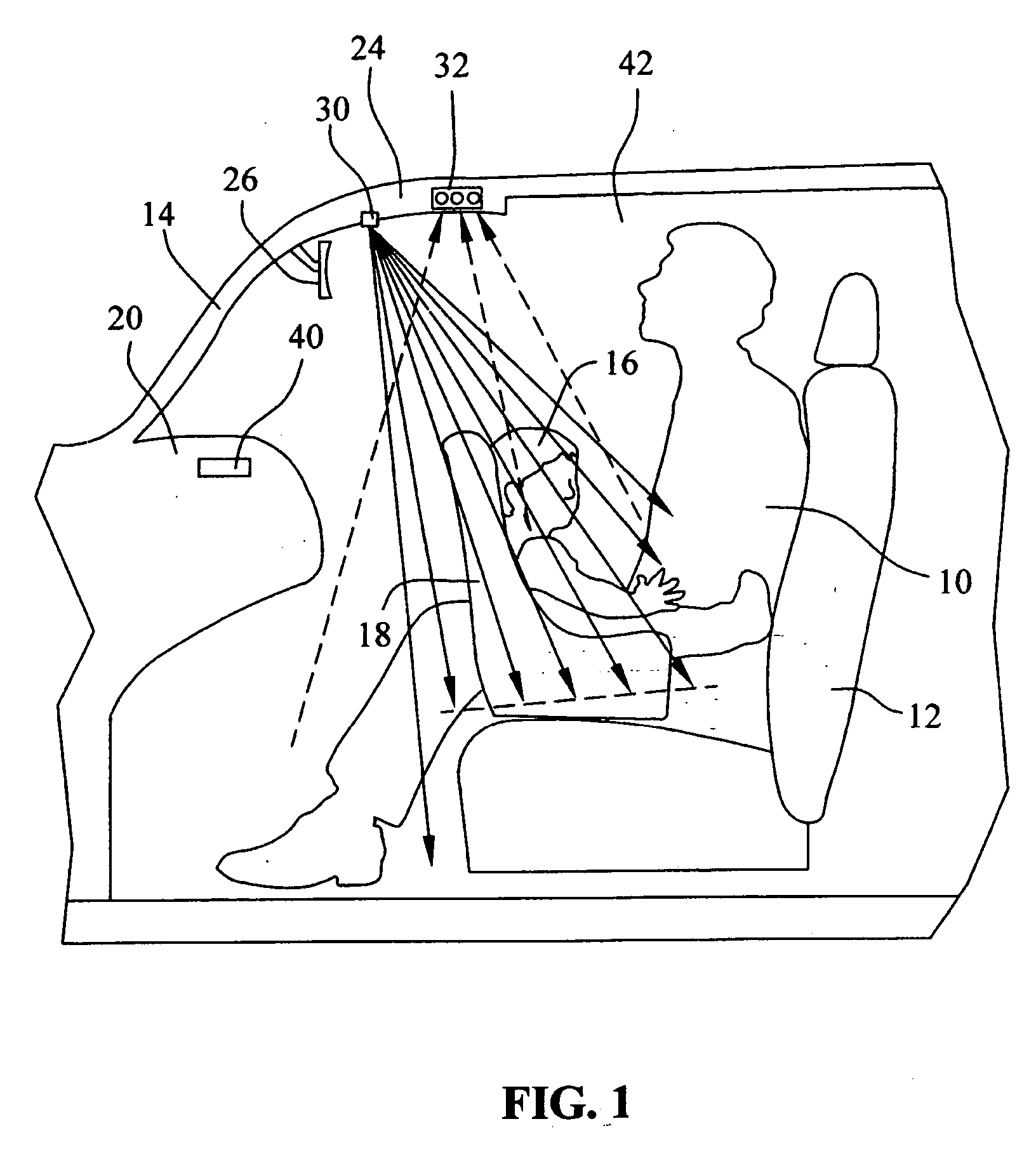
[0033] Referring now to the drawings, and particularly to FIG. 1, there is shown a person 10 seated on the front-outboard seat 12 of a vehicle 14. As shown, person 10 is properly seated on seat 12, with his hips and back placed against the back of the seat, and with the seat set at a safe distance spaced from dashboard 20 of vehicle 14. Also illustrated on FIG. 1 is an alternative arrangement in which an infant 16 is seated in a rear facing infant seat 18, clearly within the at-risk zone.

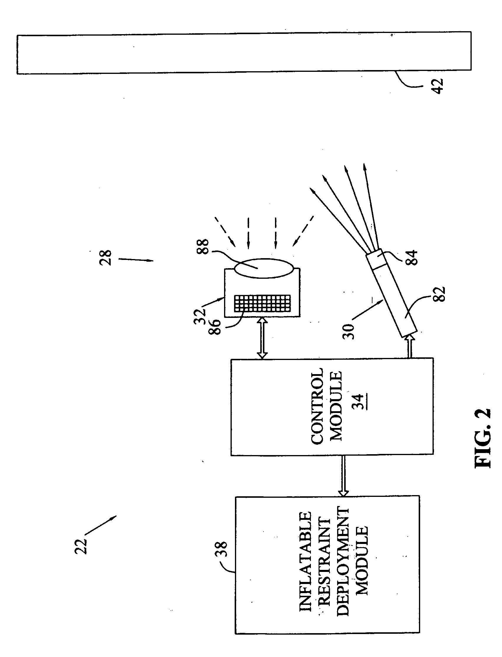
[0034] Mounted in a console 24 behind a rear view mirror 26 in vehicle 14 is an optical occupant proximity sensor system 28 (FIG. 2) including an emitter module 30 and a light detector module 32. Emitter module 30 emits optical energy in the form of infrared (IR) or near infrared (NIR) radiation. Active near infrared illuminations have the advantages of being non-intrusive to the occupants and, at the same time, providing enough sensitivity for typical silicon based receivers.

[0035] Detector modul...


PUM


Abstract

An automotive occupant position restraint apparatus senses a position of an occupant of a motor vehicle. An optical energy source emits optical energy that is substantially limited to a first range of wavelengths that corresponds to an atmospheric absorption peak. An optical energy receiver receives the optical energy emitted by the optical energy source after the optical energy has been reflected within a passenger compartment of the motor vehicle. A range of wavelengths that the receiver is operable to receive is substantially limited to a second range of wavelengths that corresponds to the atmospheric absorption peak.

Description

TECHNICAL BACKGROUND [0001] This invention relates generally to automotive optical sensing systems, and, more particularly, to a novel automotive optical sensing system that uses active illumination. BACKGROUND OF THE INVENTION [0002] While the present invention is described, for illustrative purposes, as being applied to occupant classification and position detection in a vehicle, it will be understood that it may be employed in any automotive optical sensing system that benefits from active illumination and that must function in a wide variety of ambient lighting conditions. What is meant herein by “active illumination” is that the optical sensing system provides its own source of light. Examples of such automotive optical sensing systems include active night vision systems and lane tracking systems, for example. [0003] Inflatable restraints, or air bags, are increasingly being used in vehicles to protect an occupant of a vehicle in the event of the vehicle being involved in a col...

Claims


Application Information

Patent Timeline
IPC IPC(8): G01C3/08G01S17/04
CPCG01S7/4802G01S17/026B60R21/01552B60R21/01538B60R21/01534G01S17/04
Inventor TROXELL, JOHN R.PARTIN, DALE L.KONG, HONGZHIBAUSON, WILLIAM A.SULTAN, MICHEL F.HARBACH, ANDREW P.SCHARENBROCH, GREGORY K.
Owner DELPHI TECH INC
Learn More