Radio communications system and control method therefor

Inactive Publication Date: 2006-05-04
NEC CORP
View PDF9 Cites 50 Cited by
  • Summary
  • Abstract
  • Description
  • Claims
  • Application Information

AI Technical Summary

Benefits of technology

[0012] It is an object of the present invention to provide a radio communications system which solves the problems of the prior art descr

Problems solved by technology

A change in a propagation path condition caused by a communication channel initiated at a later time, such as the uplink high-rate channel, may affect the reception quality of other existing uplink channels which have already been in service.
For example, as shown in FIG. 1, the start of a later communication through a communication channel can cause an increase in interfering power to suddenly degrade the reception quality (for example, SIR: Signal to Interference Ratio) of an earlier communication.
Also, a degradation in the reception quality of an earlier uplink communication channel can cause a disconnection of an earlier communication through the uplink channel.
Also, a degraded reception quality of an earlier uplink channel can affect a communication condition, for example, the communication quality on the earlier uplink channel.
A degraded reception quality of an earlier uplink channel can cause a disconnection of a communication through the earlier upli

Method used


Image

  • Radio communications system and control method therefor
  • Radio communications system and control method therefor
  • Radio communications system and control method therefor

Examples


first embodiment

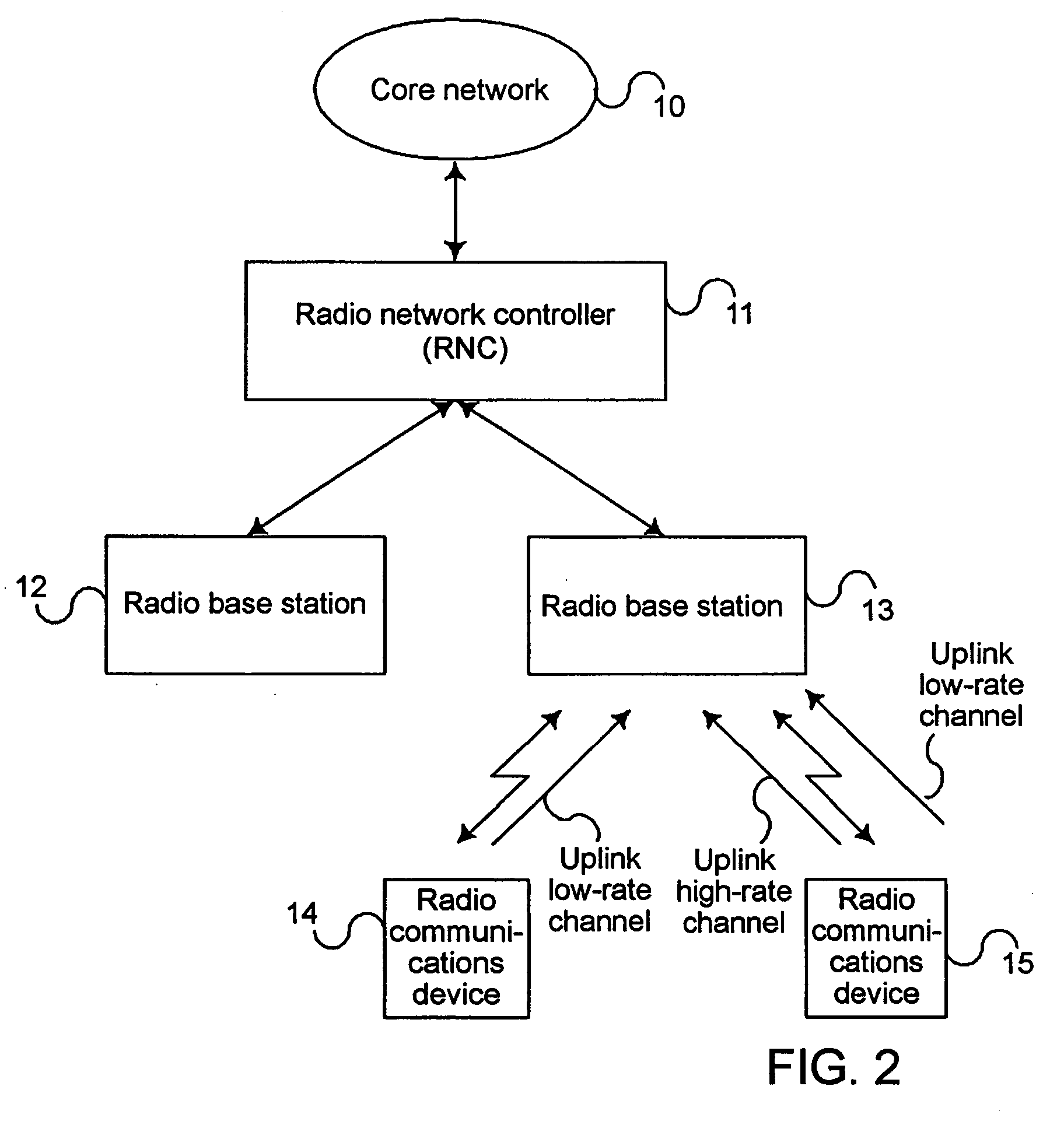
[0056]FIG. 2 is illustrates the configuration of a radio communications system according to the present invention. Note that FIG. 2 illustrates only those components which are required for describing the present invention.

[0057] The radio communications system illustrated in FIG. 2 comprises core network 10; radio network controller (RNC) 11 connected to core network 10; radio base stations (BS) 12, 13 connected to radio network controller 11; and radio communications devices 14, 15 connected to radio base stations 12, 13 through a radio channel.

[0058] As illustrated in FIG. 3, radio network controller 11 comprises transmission / reception (Tx / Rx) unit 20 for connection with a base station; control circuit 21 for controlling the operation of radio network controller 11; and transmission / reception unit 22 for connection with core network 10.

[0059] In radio network controller 11, transmission / reception unit 20 transmits a signal and / or information received from control circuit 21 to a...

second embodiment

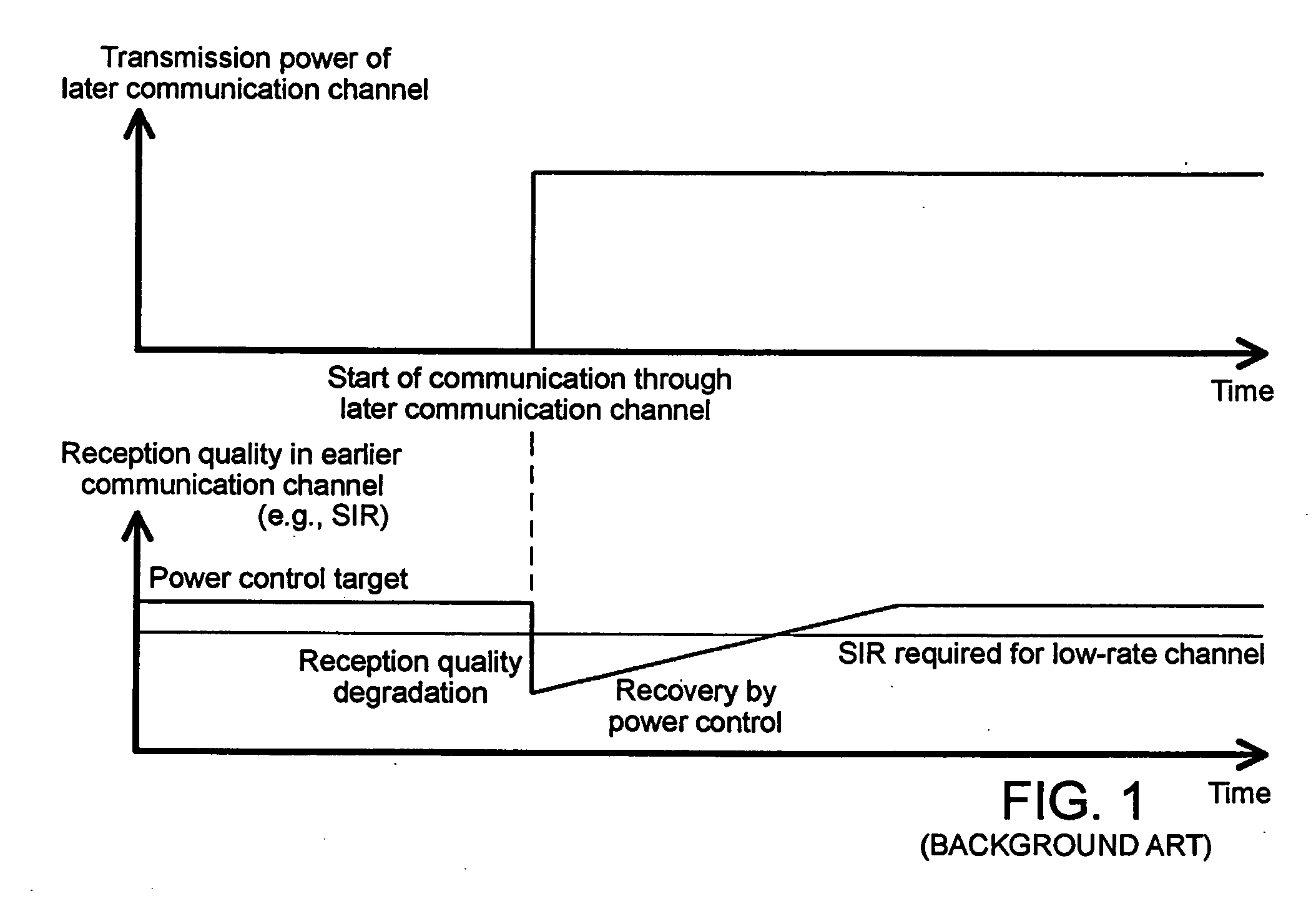
[0104] As shown in FIG. 11, in the second embodiment, the reception quality of the uplink low-rate channel will not fall short of a required reception quality with the start of a communication through the uplink high-rate channel.

[0105] In the second embodiment, the uplink high-rate channel control information may include information on a start timing of a communication through the uplink high-rate channel. In this alternative configuration, radio communications device 15 starts a communication through the uplink high-rate channel based on the information on the start timing which has been received as the uplink high-rate channel control information. Specifically, upon receipt of the information on the timing of starting a communication through the uplink high-rate channel through radio transceiver 40, control circuit 41 of radio communications device 15 starts a transmission of the uplink high-rate channel to radio base station 13 through radio transceiver 40 based on the received ...

third embodiment

[0117] In the third embodiment, steps S31 through S32 can be omitted from the processing shown in FIG. 12. In this event, radio network controller 11 starts the outer-loop power control in regard to the uplink low-rate channel at step S33 when it recognizes the start of a communication through the uplink high-rate channel. Here, radio network control circuit 11 can be configured to recognize the start of a communication through the uplink high-rate channel, for example, based on the waiting time information.

[0118] In FIG. 12, a description has been given that radio base station 13 transmits the uplink high-rate channel control information to radio communications device 15, thereby permitting the same to start a communication through the uplink high-rate channel. Alternatively, as illustrated in FIG. 13, radio base station 13 can be configured to transmit an uplink high-rate channel communication start permission notice different from the uplink high-rate channel control information,...


PUM


Abstract

A radio base station which receives a first and a second communication channel from a radio communications device comprises a control circuit for detecting the reception quality of the first communication channel, conducting an inner-loop power control for controlling transmission power of the first communication channel from the radio communications device based on the reception quality and an inner-loop power control target value, and adding a power control offset to the inner-loop power control target value before starting a communication through the second communication channel.

Description

BACKGROUND OF THE INVENTION [0001] 1. Field of the Invention [0002] The present invention relates to transmission power control for a communication channel in a radio communications system. [0003] 2. Description of the Related Art [0004] In radio communications systems, considerations have been made on the transmission of a variety of contents including video clips, multimedia data, games, streaming videos and the like. Commercialization of such a transmission system entails a reduction in delay in uplink communications, an enlargement of a coverage area, and an improvement in throughput in the radio communications systems. The introduction of communications on uplink high-rate communication channels have been under investigation as a communications scheme suitable for such systems. Such a communication scheme is defined in a standard such as 3GPP TR 25.896 V6.0 by 3GPP (3rd Generation Partnership Project). [0005] Technologies have been desired for realizing a service using uplink h...

Claims


Application Information

Patent Timeline
IPC IPC(8): H04B7/185H04W52/12H04W52/16H04W52/24H04W52/26H04W52/36H04W52/50
CPCH04W52/12H04W52/16H04W52/24H04W52/243H04W52/26H04W52/36H04W52/50
Inventor KONDOU, DAISUKEIWASAKI, MOTOYAKAWABATA, HISASHINISHIMURA, OSAMIHASEBA, YUKIOSAKUMA, EMIKO
Owner NEC CORP
Why Eureka
Try Eureka