

Dual drum type continuous casting device and method for continuous casting
- Summary
- Abstract
- Description
- Claims
- Application Information
AI Technical Summary
Benefits of technology
Problems solved by technology
Method used
Image

Examples
first embodiment
[First Embodiment]
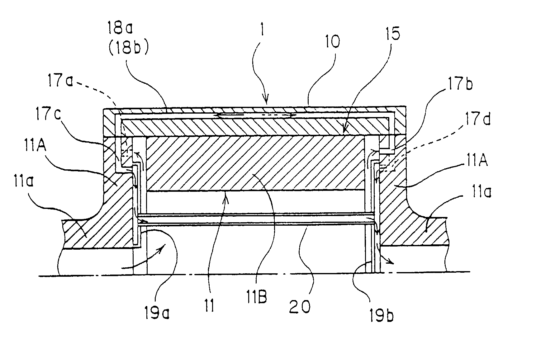
[0100]FIG. 1 is a sectional view of an internal structure of a cooling drum showing a first embodiment of the present invention. FIG. 2 is an explanation drawing of a surface pressure distribution at fitting surfaces of an end portion of the cooling drum.
[0101]As shown in FIG. 1, a cooling drum 1 includes a drum body 11 having hollow shaft portions 11a at opposite end portions, and a drum sleeve 10 fitted on an outer peripheral portion of the drum body 11. The drum body 11 is formed from, and divided into, a pair of shaft members 11A having the hollow shaft portions 11a formed integrally therewith and being joined to end portions of the drum sleeve 10, and a core member 11B located between the shaft members 11A and shrink fitted to an inner peripheral surface of the drum sleeve 10 without contacting the shaft members 11A.
[0102]The drum sleeve 10 uses a material (e.g., a copper alloy) provided with high strength by solution heat treatment, followed by cold forging a...
second embodiment
[Second Embodiment]
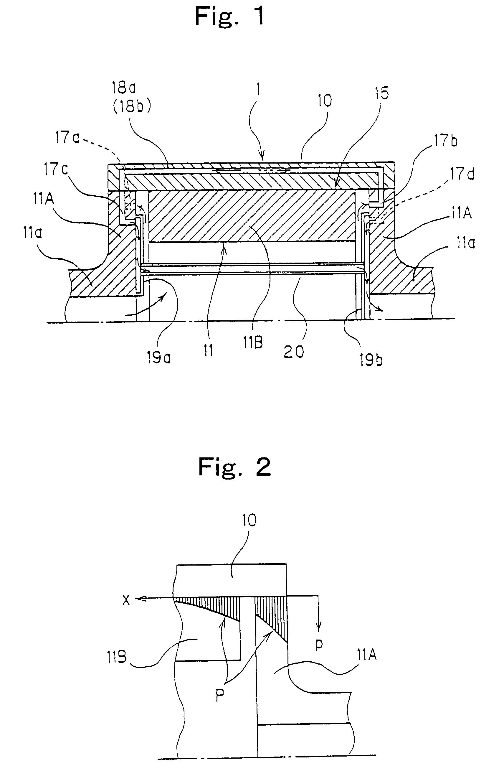
[0110]FIG. 3 is a sectional view of an internal structure of a cooling drum showing a second embodiment of the present invention.
[0111]This is an embodiment in which the wall thickness of the intermediate portion in the drum axis direction of the core member 11B, where a tightening margin for shrink fit is to be increased, is made larger than the wall thickness of the end portion to maintain a high contact pressure resistance. This embodiment shows the same effects as does the First Embodiment.
third embodiment
[Third Embodiment]
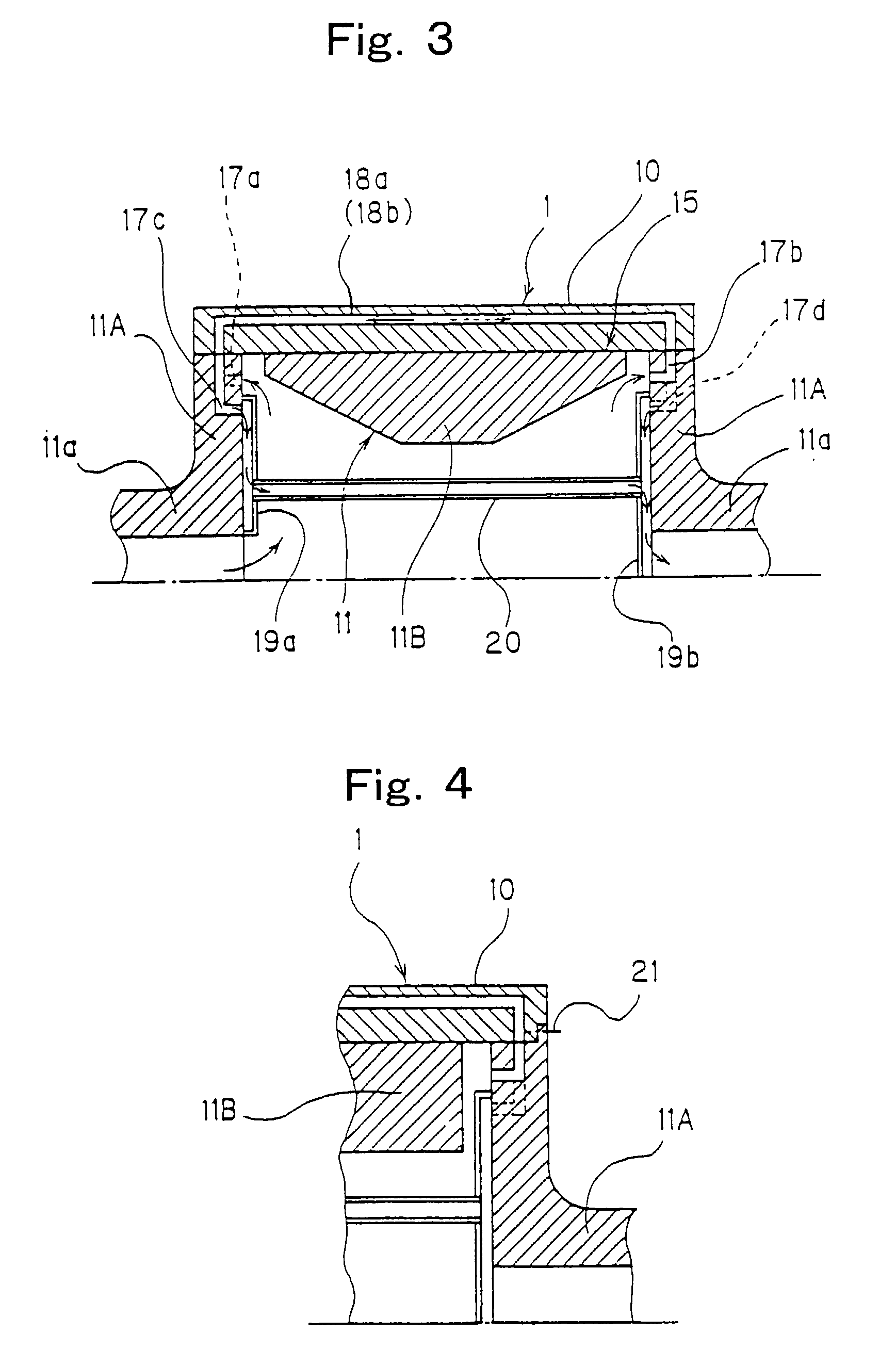
[0112]FIG. 4 is a sectional view of an end structure of a cooling drum showing a third embodiment of the present invention.
[0113]This is an embodiment in which the method for joining of the drum sleeve 10 and the shaft member 11A is changed from shrink fit to tightening by a bolt 21. According to this embodiment, the tightening margin at the fitting surfaces can be decreased. Thus, the advantage that the attachment and detachment of the shaft member 11A are easy is obtained, in addition to the same effects as in the First Embodiment.
PUM
| Property | Measurement | Unit |
|---|---|---|
| Thickness | aaaaa | aaaaa |
| Temperature | aaaaa | aaaaa |
| Thickness | aaaaa | aaaaa |
Abstract
Description
Claims
Application Information