
Ultrasound beamformer with high speed serial control bus packetized protocol

Inactive Publication Date: 2006-05-04
GENERAL ELECTRIC CO
View PDF42 Cites 42 Cited by
  • Summary
  • Abstract
  • Description
  • Claims
  • Application Information

AI Technical Summary

Benefits of technology

[0010] A protocol for formatting control information is provided for conveying the formatted control information to a processing component of a beamformer within an ultrasound system. The processing component has a unique identifier. The protocol provides for an address packet formatted in accordance with a packetized protocol, the address packet containing control information associated with the processing component to which the control information is directed. The protocol further provides a data packet formatted to contain control information related to beamfor

Problems solved by technology

Heretofore, limited communications capabilities existed between the distributed processing within the beamformer and the central control of the beamformer.
Existing systems experienced limitations in the amount and type of control information that could be processed by the electronics within the beamformer.

Method used


Image

  • Ultrasound beamformer with high speed serial control bus packetized protocol
  • Ultrasound beamformer with high speed serial control bus packetized protocol
  • Ultrasound beamformer with high speed serial control bus packetized protocol

Examples


Embodiment Construction

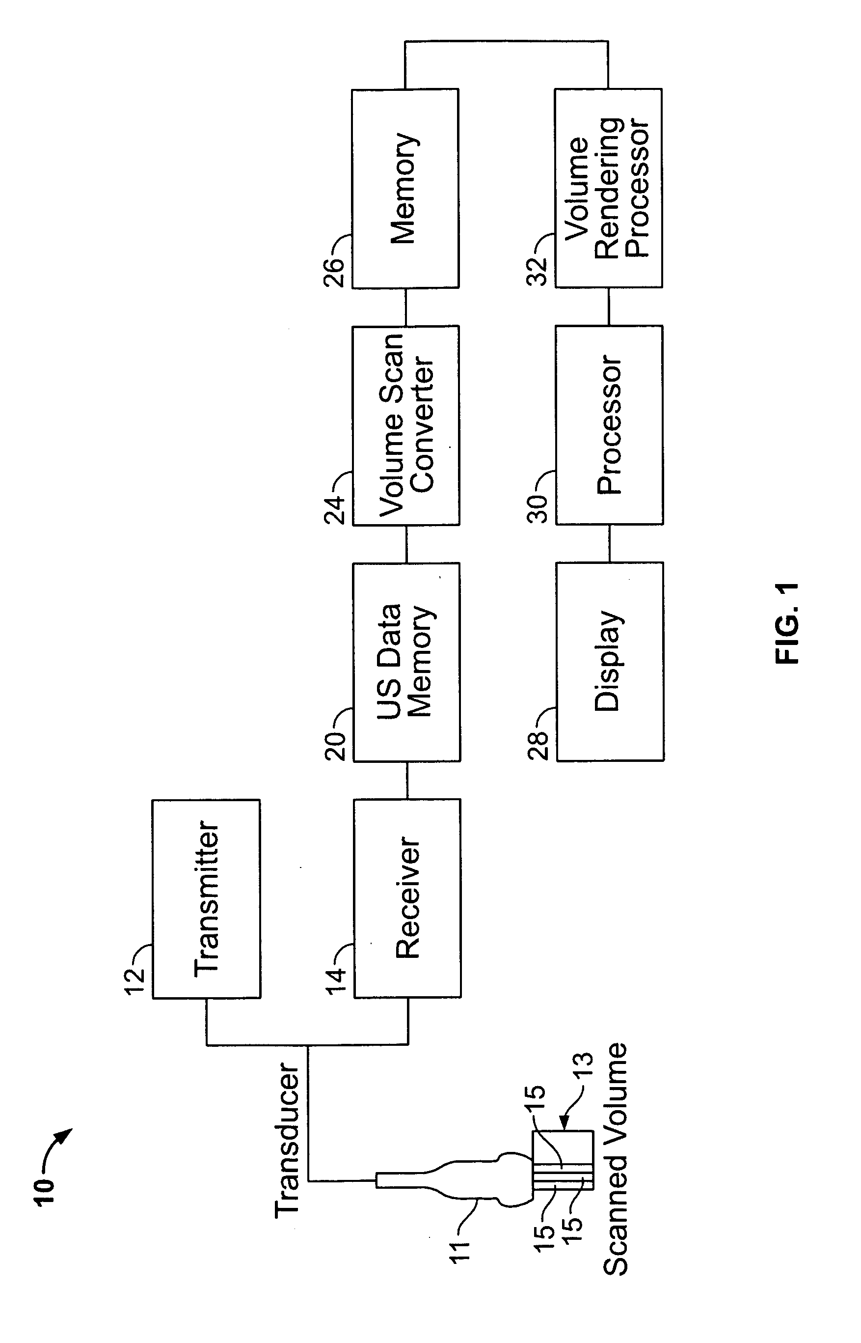
[0019]FIG. 1 illustrates an ultrasound system 10 formed in accordance with one embodiment of the present invention. The system 10 includes a probe 11 connected to a transmitter 12 and a receiver 14. The probe 111 transmits ultrasonic pulses and receives echoes from structures inside of a scanned ultrasound volume 13. Memory 20 stores ultrasound data from the receiver 14 derived from the scanned ultrasound volume 13. The volume 13 may be obtained by various techniques (e.g., 3D scanning, real-time 3D scanning, 2D scanning with transducers having positioning sensors, freehand scanning using a voxel correlation technique, 1.25D, 1.5D, 1.75D, 2D or matrix array transducers and the like).

[0020] The probe 11 is moved, such as along a linear or arcuate path, or electronically steered when using a 2D array, while scanning a region of interest (ROI). At each linear or arcuate position, the probe 11 obtains scan planes 15. The scan planes 15 are stored in the memory 20, and then passed to a ...


PUM


Abstract

A method for conveying control information in an ultrasound system is provided. The method provides unique identifiers for the processing components in a beamformer of an ultrasound system. The method formats control information into at least one packet based on a packetized protocol, the control information relating to beamforming operations carried out by the processing components. The method conveys the control information to the processing components.

Description

BACKGROUND OF THE INVENTION [0001] The invention relates generally to various aspects of a beamformer (BF) for an ultrasound system. [0002] In conventional ultrasound systems, a variety of beamformer (BF) designs have been proposed to perform the functions of the beamformer associated with the signals transmitted to and received from transducer elements of an ultrasound probe. The beamformer performs signal processing on a matrix of input signals received from a number of the transducer elements in the probe. The transducer elements transmit (fire) ultrasound pulses to scan a region of interest and generate input signals when the transducer elements receive ultrasound echoes from the region of interest in response to the ultrasound scan. Conventional beamformers combine at least subsets of the matrix of input signals to form one or more BF receive beams. The input signal received from each transducer is referred to as a transducer channel and multiple transducer channels are combine...

Claims


Application Information

Patent Timeline
IPC IPC(8): H04L12/56
CPCH04L67/125
Inventor SHAH, SNEHAL CHANDRAKANT
Owner GENERAL ELECTRIC CO
Features
  • Generate Ideas
  • Intellectual Property
  • Life Sciences
  • Materials
  • Tech Scout
  • Unparalleled Data Quality
  • Higher Quality Content
  • 60% Fewer Hallucinations
Learn More