Method and system for generating shared information

a technology of shared information and information, applied in the field of communication systems, can solve the problems of loss of synchronization of bits, large error rate of reception data, and significant degraded common-key generation efficiency, and achieve the effect of stable and fast key generation ra

Active Publication Date: 2006-05-04
NEC CORP
View PDF4 Cites 36 Cited by
  • Summary
  • Abstract
  • Description
  • Claims
  • Application Information

AI Technical Summary

Benefits of technology

[0010] An object of the present invention is to provide a method and system for stably and efficiently generating shared information between communication devices.
[0011] Another object of the present invention is to provide a method and system that can achieve the efficient sharing of information by the prompt establishment of bit position synchronization.
[0018] According to the present invention, the bit positions of shared information set by a general scheme can be changed depending on whether the bit positions are in synchronization or out of synchronization. Accordingly, even in the case where the bit positions are out of synchronization, bit positions (e.g. bit numbers) are reassigned to the received bits, and shared information is regenerated, whereby synchronization determination can be performed again without terminating the key generation flow.
[0019] According to the present invention, in a quantum key distribution system for example, even in the case where synchronization is lost, synchronization determination can be performed by utilizing a raw key generated by single-photon transmission, without reestablishing synchronization. Accordingly, it is possible to achieve a stable, fast key generation rate.

Problems solved by technology

However, according to the above-mentioned conventional methods, there remains a possibility that the bit positions lose synchronization due to the expansion and contraction of a transmission line and processing deviations occurring in devices involved.
In this circumstance, all the key that has been generated by single-photon transmission comes to nothing, resulting in a significantly degraded efficiency in common-key generation.
Similarly, according to the method described in Japanese Patent Application Unexamined Publication No. 2004-112278, when the bit positions lose synchronization, the error rate of the reception data becomes very large, resulting in it being impossible to generate a common key.
Additionally, no consideration is given to the processing to be performed when the error rate is large.

Method used


Image

  • Method and system for generating shared information
  • Method and system for generating shared information
  • Method and system for generating shared information

Examples


first embodiment

1. First Embodiment

(System Configuration)

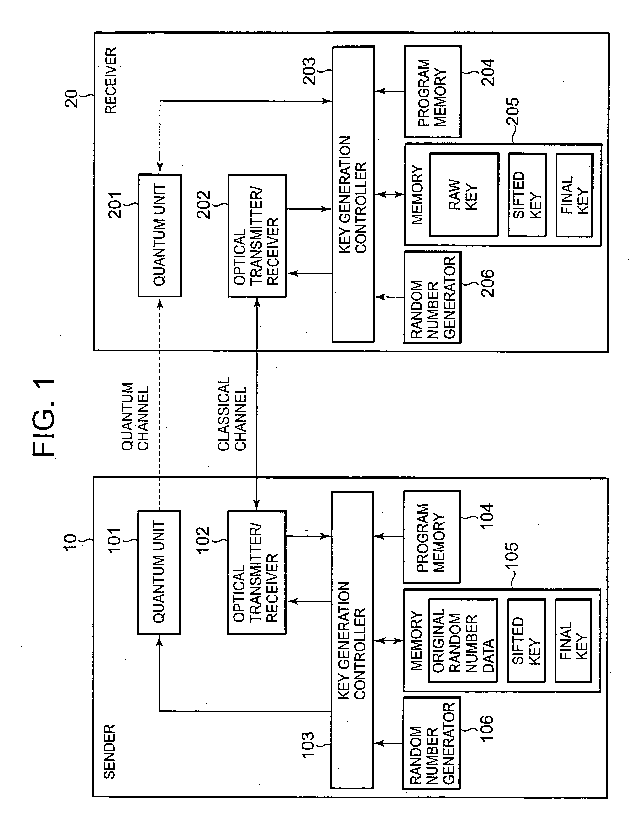
[0034]FIG. 1 is a block diagram showing a configuration of a quantum key distribution system according to a first embodiment of the present invention. Referring to FIG. 1, the quantum key distribution system includes a sender 10 and receiver 20, which are connected by a quantum channel and a classical channel. Here, the quantum channel is a communication channel in a state where the optical power for transmission from the sender 10 to the receiver 20 is very weak, at the level of at most one photon per bit, whereas the classical channel is a communication channel in a range of optical power that is used in usual (conventional or usually used) optical communication.

[0035] The sender 10 is provided with a quantum unit 101 for single-photon transmission and an optical transmitter / receiver 102 for usual optical communication. The quantum unit 101 and the optical transmitter / receiver 102 are controlled by a key generation controller 103 that ex...

second embodiment

2. Second Embodiment

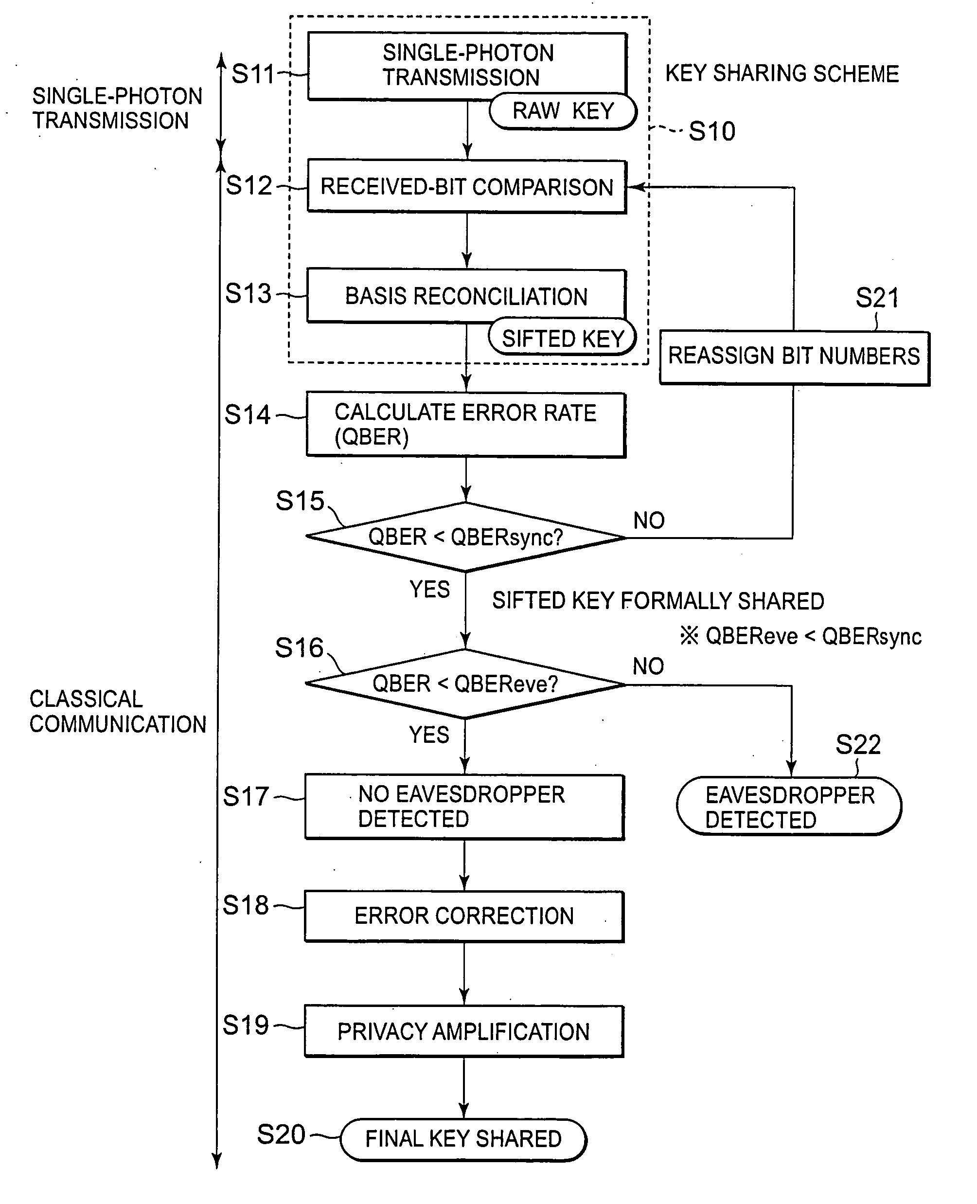
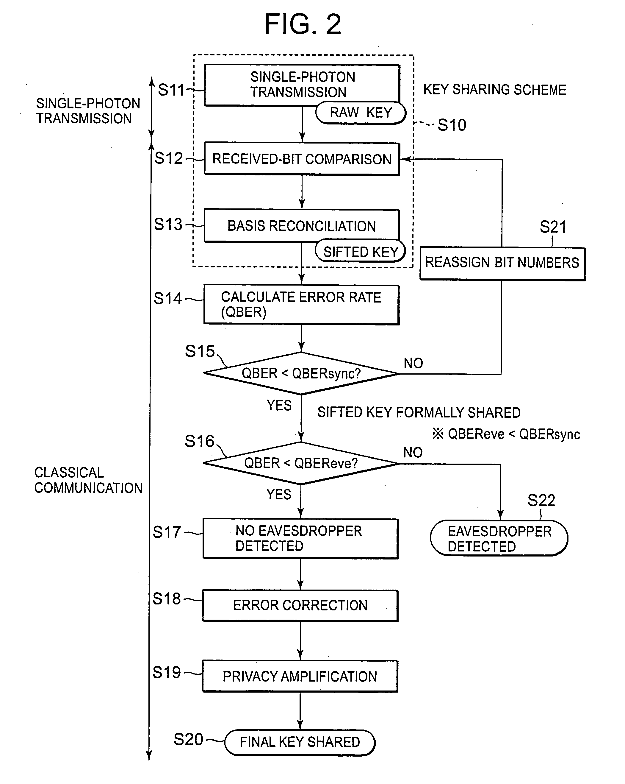
[0068] In the first embodiment, as described above, when QBER≧QBERsync in the step S15 in FIG. 2, it is determined that bit position synchronization is not established, and a notification to that effect (NG) is sent from the sender 10 to the receiver 20. Then, the bit number reassignment step S21 is performed on the receiver side. As another method, it is possible to perform this bit number reassignment step S21 on the sender side.

[0069]FIG. 10 is a sequence diagram showing operations for sifted key settlement according to a second embodiment of the present invention. The general flow in the second embodiment is as described in conjunction with FIG. 2, and therefore a detailed description thereof will be omitted.

[0070] First, when a raw key is generated on the receiver side by single-photon transmission (step S11 in FIG. 2), the receiver 20 sends received-bit numbers assigned to the bits of the raw key, which were able to be received, and basis information corr...

third embodiment

3. Third Embodiment

[0073] The quantum units 101 and 102 for single-photon transmission and the optical transmitters / receivers 102 and 202 for usual optical communication in FIG. 1 are not limited to a specific scheme. Hereinafter, as a preferred embodiment, a quantum key distribution system in plug and play scheme will be described. The plug and play scheme is regarded as one of the promising schemes for putting the polarization-sensitive quantum key distribution systems to practical use, because the plug and play scheme can compensate polarization fluctuations occurring over an optical fiber transmission line.

[0074]FIG. 11 is a block diagram showing a configuration of a quantum key distribution system in the plug and play scheme according to a third embodiment of the present invention. The quantum key distribution system according to this embodiment includes a sender 10, a receiver 20, a sender-side wavelength multiplexer / demultiplexer 30, and a receiver-side wavelength multiplexe...


PUM


Abstract

A sender sends original random-number data to a receiver through a quantum channel. The receiver generates a raw key from information received through the quantum channel and notifies the received information to the sender. The sender performs received-bit comparison and basis reconciliation based on the received information and provisionally shares a sifted key with the receiver. The receiver sends part of its version of the sifted key to the sender, by which an error rate is calculated. The calculated error rate is compared with a predetermined threshold value for bit position synchronization determination. When the calculated error rate is larger, the sender notifies the receiver that bit position synchronization is not established. The receiver reassigns bit numbers to the sifted key, and received-bit comparison and basis reconciliation are performed again. This procedure is repeated until the calculated error rate becomes smaller than the threshold value.

Description

BACKGROUND OF THE INVENTION [0001] 1. Field of the Invention [0002] The present invention relates to a communication system using a communication channel that is relatively less reliable in communication and a communication channel that is relatively highly reliable in communication. Particularly, the present invention relates to a method and system for generating secret information shared between a sender and a receiver. [0003] 2. Description of the Related Art [0004] In the field of quantum cryptography, based on Heisenberg's uncertainty principle, it is known that eavesdropping between a sender and a receiver can be detected with high probability. Conversely, this fact indicates that a sender and a receiver can share a secret bit string (cryptographic key) without being eavesdropped. For a procedure to share secret information, for example, the BB84 (Bennett Brassard 84) protocol using four quantum states is known as well as other protocols. A high level of security can be achiev...

Claims


Application Information

Patent Timeline
Patent Type & Authority Applications(United States)
IPC IPC(8): H04K1/00H04B10/25H04B10/27H04B10/524H04B10/556H04B10/70H04J14/00H04J14/02H04L9/08H04L9/12
CPCH04L9/0852H04L2209/34
Inventor MAEDA, WAKAKOTAJIMA, AKIOTANAKA, AKIHIRO
Owner NEC CORP
Why Eureka
Try Eureka