Wireless communication module, communication terminal, and impedance matching method

a technology of impedance matching and communication terminal, which is applied in the direction of power management, transmitter monitoring, transmission monitoring, etc., can solve the problems of inability to carry out accurate impedance matching, increase the size of communication terminals and the like, etc., and achieve the effect of easy impedance matching with the antenna, and minimal circuit construction

Inactive Publication Date: 2006-05-04
HANEI
View PDF16 Cites 52 Cited by
  • Summary
  • Abstract
  • Description
  • Claims
  • Application Information

AI Technical Summary

Benefits of technology

[0027] With this, by only detecting the transmission power of the transmitter, it is possible to attain impedance matching, thereby making it possible to achieve a minimal circuit construction without addition of special circuits.
[0028] In the present invention, impedance matchi...

Problems solved by technology

In the above-described conventional technique, impedance matching requires an addition of a phase detecting circuit, a voltage standing wave ratio (VSWR) detecting circuit and the like to the circuit, resulting in problems such as increased size of the communication terminal and the like.
There is another problem in that in a wireless communication modu...

Method used


Image

  • Wireless communication module, communication terminal, and impedance matching method
  • Wireless communication module, communication terminal, and impedance matching method
  • Wireless communication module, communication terminal, and impedance matching method

Examples


first embodiment

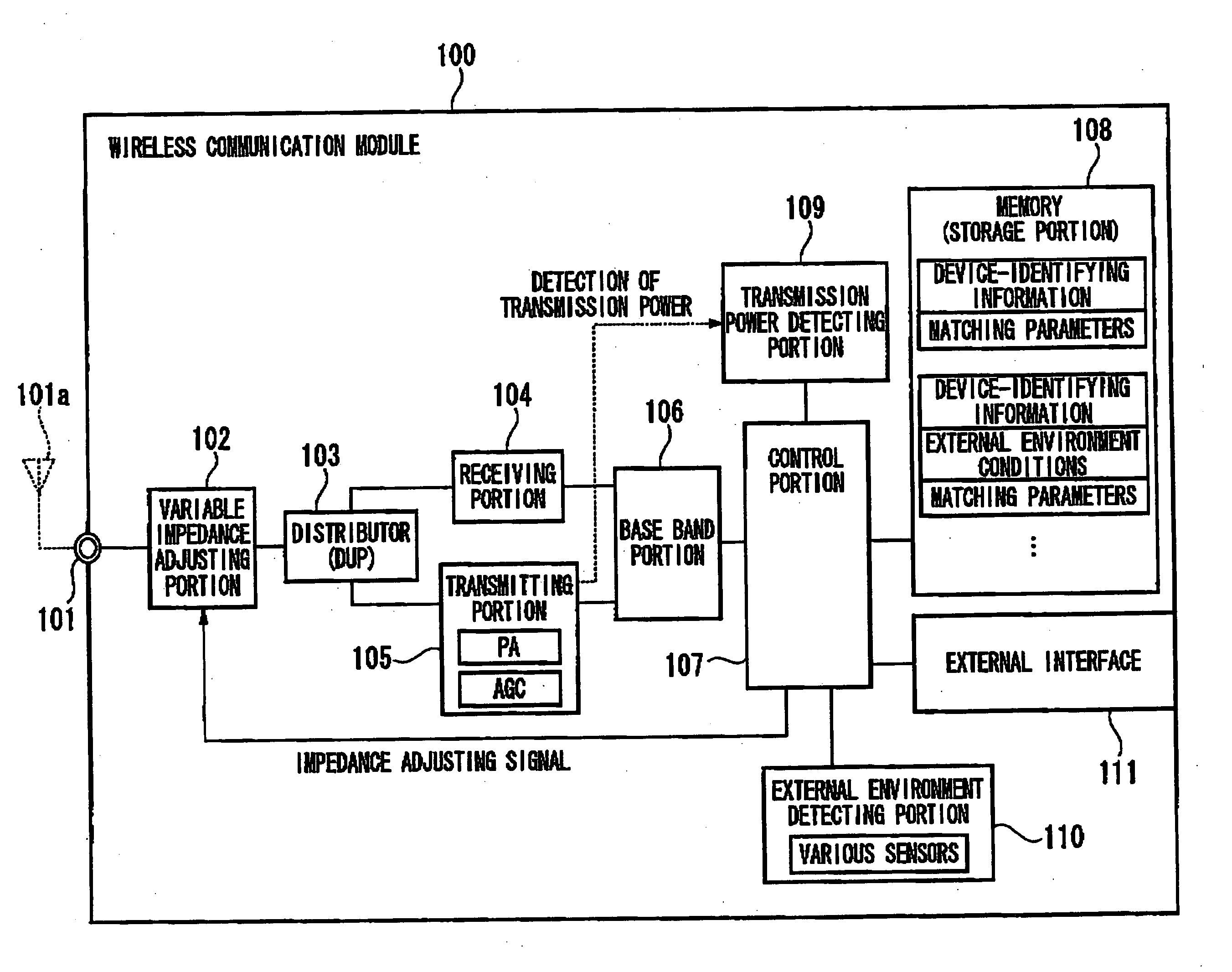
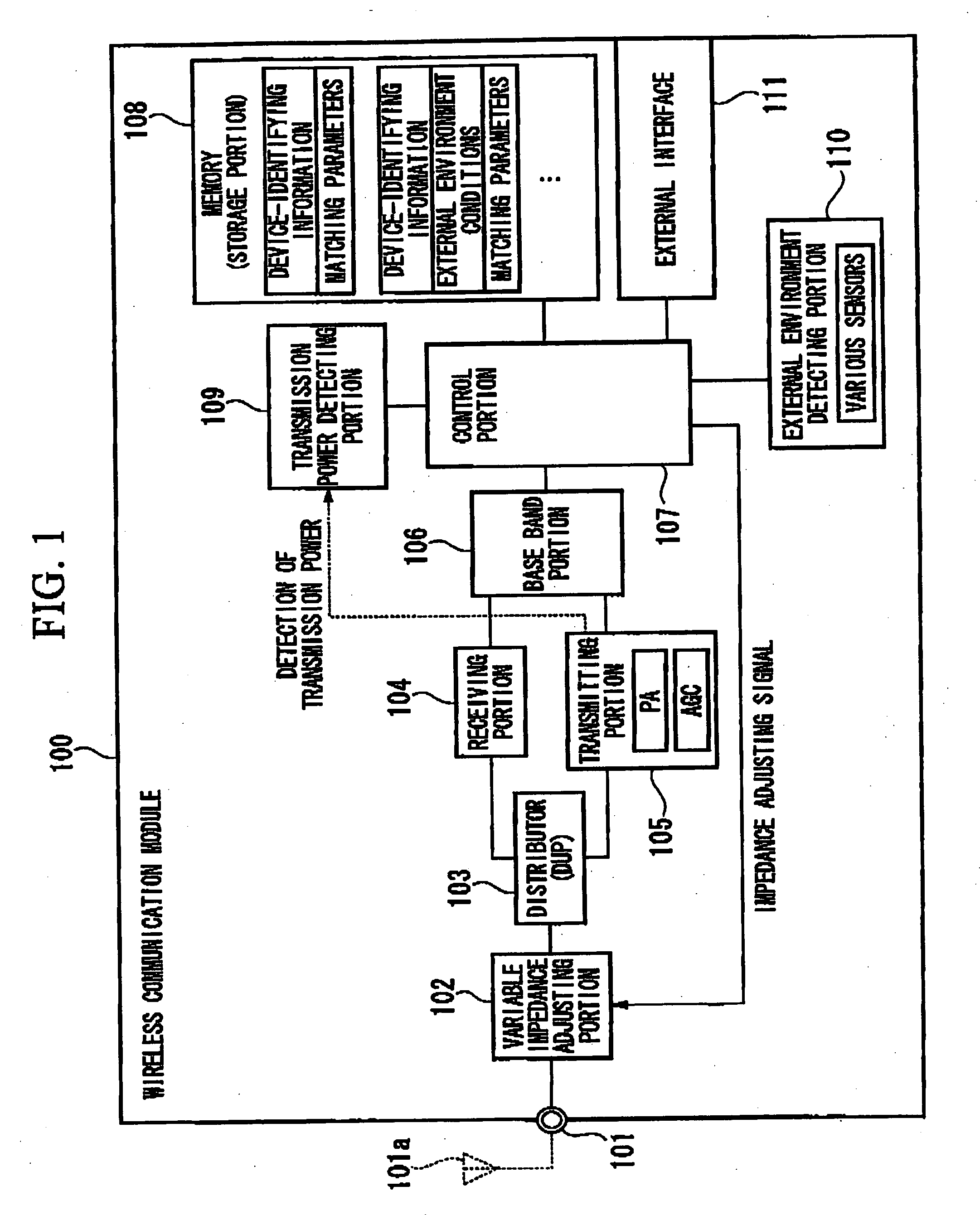
[0036]FIG. 1 is a schematic block diagram showing a wireless communication module having an external antenna according to a first embodiment of the present invention, in which transmission power of a wireless communication module 100 is controlled by a base station (not shown) so that the transmission power from the wireless communication module 100 can be received at an appropriate level by the base station.

[0037] In FIG. 1, the wireless communication module 100 includes an antenna connection portion (antenna connector) 101, a variable impedance matching portion (variable impedance matching section) 102 having variable impedance (for example, condenser capacity and inductance) which can be adjusted, a distributor (DUP) 103 for distributing signals transmitted or received, a receiving portion (receiver) 104, a transmitting portion (transmitter) 105, a base band portion 106 for controlling communications, a control portion (controller) 107, a memory 108, a transmission power detecti...

second embodiment

[0062]FIG. 5 is a schematic block diagram showing a communication terminal of a second embodiment in the present invention, showing a portable mobile phone as an example of the communication terminal. In the example shown in FIG. 5, the transmission power of a portable mobile phone 200 is controlled by a base station in such a way that the transmission power from the portable mobile phone 200 can be received at an appropriate level by the base station (not shown).

[0063] The portable mobile phone 200 includes an antenna 201, a variable impedance matching portion 202 having variable impedance which can be adjusted, a distributor (DUP) 203 for distributing signals transmitted or received, a receiving portion 204, a transmitting portion 205, a base band portion 206 for controlling communications, a control portion 207, a memory 208, a transmission power detecting portion 209 for detecting the transmission power of the transmitting portion 205, and an external environment detecting port...


PUM


Abstract

A wireless communication module for engaging in communications with a base station, the wireless communication module being incorporated into an information device having an antenna, includes a transmitter, a transmission power being controlled by the base station; variable impedance matching section arranged between an antenna connector connected to the antenna and the transmitter, which adjusts an impedance by changing a matching parameter for the variable impedance matching section; transmission power detector for detecting the transmission power; and a controller for adjusting the matching parameter based on the detected transmission power of the transmitter detected by the transmission power detector.

Description

BACKGROUND OF THE INVENTION [0001] 1. Field of the Invention [0002] The present invention relates to a wireless communication module, a communication terminal, and an impedance matching method. More specifically, the present invention relates to technology of matching impedance with an antenna in a wireless communication module incorporated into an information device (for example, a PDA). [0003] Priority is claimed on Japanese Patent Application No. 2004318019, filed Nov. 1, 2004, the content of which is incorporated herein by reference. [0004] 2. Description of the Related Art [0005] In a communication terminal such as a portable mobile phone in which an antenna is equipped, in gene, circuits are designed so as to match an antenna with an RF circuit (radio amplifying circuit) in a range of the frequencies used. In wireless communication modules, a matching circuit is typically designed so as to be incorporated into an information device. Since there may be a mismatch due to the inf...

Claims


Application Information

Patent Timeline
IPC IPC(8): H04B7/00
CPCH04B1/0458H04B2001/0416H04B17/18H04B17/102H04W52/08H04B1/12H04B1/18H04B1/40
Inventor KITAJI, MITSUHIRO
Owner HANEI
Why Eureka
Try Eureka