Method for operating a mass flow meter

a mass flow meter and flowmeter technology, applied in the direction of direct mass flow meter, liquid/fluent solid measurement, instruments, etc., can solve the problem of requiring a greater processing effort, and achieve the effect of high degree of accuracy

Active Publication Date: 2006-05-11
KRONE GMBH
View PDF7 Cites 51 Cited by
  • Summary
  • Abstract
  • Description
  • Claims
  • Application Information

AI Technical Summary

Benefits of technology

[0007] While the physical-mathematical model for the dynamics of the mass flowmeter is to encompass at least the dynamics of the oscillating measuring tube, it can additionally represent other constituent devices of the mass flowmeter as well. Thus, in a preferred embodiment of the invention, the physical-mathematical model serving to determine density values is not only based on the dynamics of the measuring tube but also factors-in the effect of at least one other component of the measuring tube system, such as a support pipe and / or the measuring-tube suspension of the mass flowmeter. In this case, factoring-in additional components of the mass flowmeter in building the physical-mathematical model for the dynamics of the mass flowmeter provides a more complete representation of the actual device which, on the other hand, because of the more complex model, entails a greater processing effort.
[0018] In a preferred embodiment of the invention, designed to permit the inclusion of all the capabilities referred to above, the temperature in the mass flowmeter is measured to allow compensation for the temperature dependence of the function of at least one component of the mass flowmeter system, such as an oscillation generator for the measuring tube and / or an oscillation sensor for the measuring tube. This allows correction for thermal effects in the density measurements that would not otherwise be included in the physical-mathematical model.
[0019] Another preferred embodiment of the invention also provides for the temperature of the measuring tube to be gauged so as to permit compensation in the density measurements for a thermally induced change in the volume of the measuring tube. Finally, in a preferred implementation of the invention, the pressure inside the measuring tube is determined so as to permit compensation in the density measurements for pressure-related changes in the volume of the measuring tube. It is thus possible to further improve the accuracy in measuring the density of the medium flowing through the measuring tube. In the preferred implementation of the invention last mentioned, pressure measurements can be performed in direct fashion using a pressure sensor or indirectly, for instance by monitoring the elastic constant of the measuring tube.

Problems solved by technology

In this case, factoring-in additional components of the mass flowmeter in building the physical-mathematical model for the dynamics of the mass flowmeter provides a more complete representation of the actual device which, on the other hand, because of the more complex model, entails a greater processing effort.

Method used


Image

  • Method for operating a mass flow meter
  • Method for operating a mass flow meter
  • Method for operating a mass flow meter

Examples


Embodiment Construction

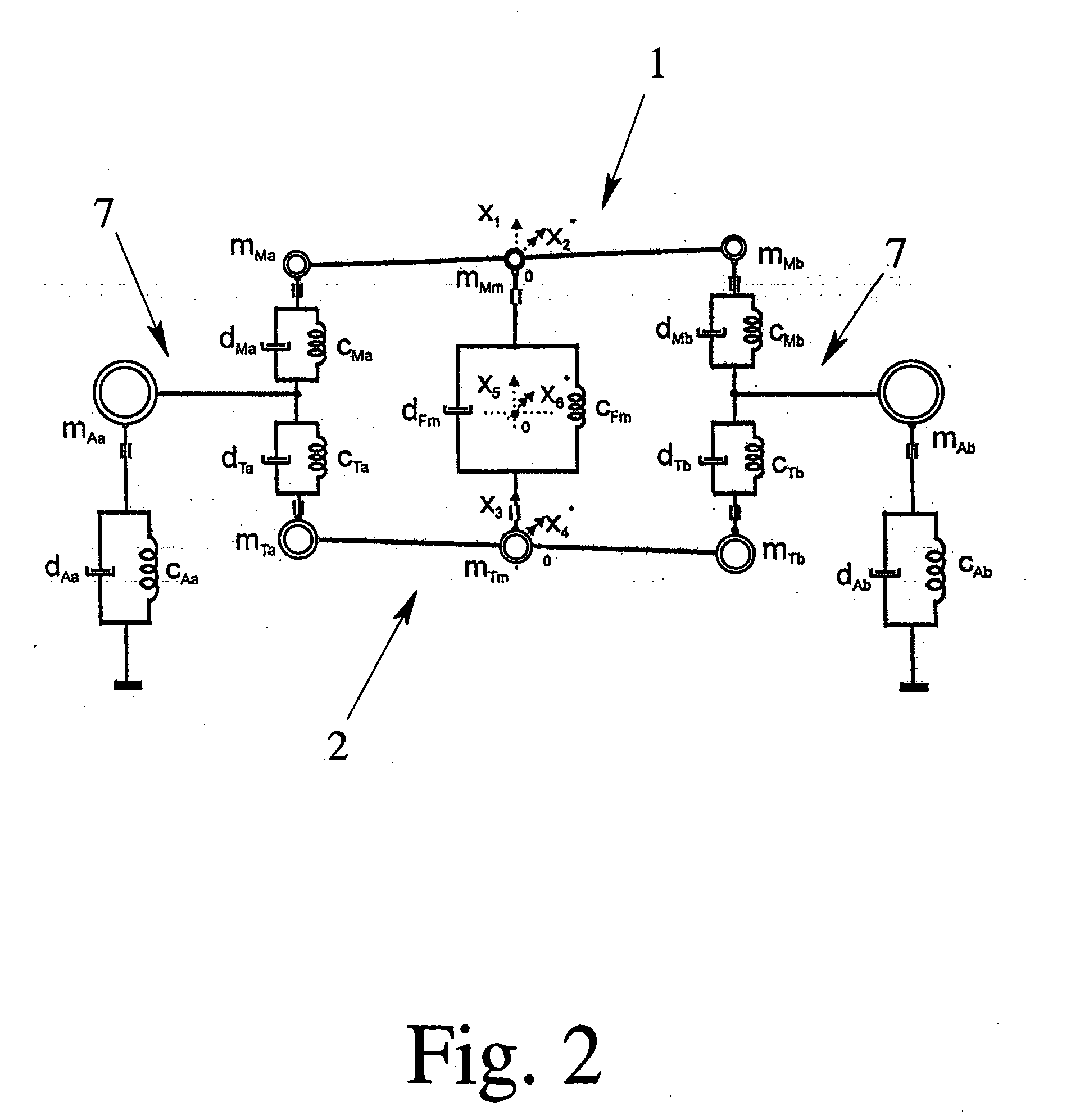
[0024] Conventional mass flowmeters employing the Coriolis principle are often operated by the natural self-resonance method. This also permits measuring the density of the medium flowing through the measuring tube. The measuring base is the assumed model for an oscillating elastic mass system where the radian frequency ωO is: ω0=cm(1)

where c is the effective elasticity constant of the oscillator and its mount and m is the effective oscillating mass. This oscillating mass is composed of the oscillator itself and of its content, if any, and thus:

m−mP+mF  (2)

If in the case of the measuring tube of a Coriolis mass flowmeter the content consists of a flowing medium, the mass mF of the medium is equal to the product of its density ρF and the volume VF of the measuring tube;

mF=ρFVF  (3)

If one substitutes for the oscillating mass the effective mass of the empty oscillator mP and of the flowing medium, the result will be the following defining equation for determining the density of...


PUM


Abstract

A method for operating a mass flowmeter that employs the Coriolis principle and through which flows a medium, wherein the mass flowmeter incorporates a measuring tube that can be stimulated to oscillate, the measuring tube is stimulated to oscillate at a minimum of two mutually different frequencies and / or in at least two mutually different natural oscillating modes, and the resulting oscillations of the measuring tube are recorded. The density of the medium flowing through the measuring tube is determined by evaluating the acquired oscillations of the measuring tube on the basis of a physical-mathematical model for the dynamics of the mass flowmeter. In this fashion, highly accurate measurements are obtained for determining the density of the medium flowing through the measuring tube.

Description

BACKGROUND OF THE INVENTION Field of the Invention [0001] This invention relates to a method for operating a mass flowmeter that employs the Coriolis principle and encompasses a measuring tube through which flows a medium, whereby the measuring tube is energized to oscillate at a minimum of two mutually different frequencies and / or in at least two mutually different natural oscillating modes, and the resulting oscillations of the measuring tube are measured. [0002] A similar method has been described earlier for instance in DE 100 02 635 A1. According to that document, the measuring tube is stimulated in three mutually different oscillating modes, and by means of the recorded oscillatory response pattern of the measuring tube, the characteristic values of the mass flowmeter such as its zero point and its sensitivity are determined, in real-time during the operation of the mass flowmeter, with the aid of a mathematical-physical model. [0003] Determining the zero point and sensitivity...

Claims


Application Information

Patent Timeline
Patent Type & Authority Applications(United States)
IPC IPC(8): G01F1/84
CPCG01F1/8404G01F1/8413G01F1/8431G01F1/8436G01F1/849G01N2009/006
Inventor KOLAHI, KOUROSHSCHRODER, THORSTENSTORM, RALF
Owner KRONE GMBH
Why Eureka
Try Eureka