Corner molding and stop assembly for collapsible shelter

a shelter and corner molding technology, applied in the field of shelters, can solve the problems of buckling, overextension or misalignment of truss sections, and light weight design is not always as stable as its heavier counterparts, and achieve the effect of high efficiency in us

Inactive Publication Date: 2006-05-11
GO PAPA LLLP
View PDF29 Cites 47 Cited by
  • Summary
  • Abstract
  • Description
  • Claims
  • Application Information

AI Technical Summary

Benefits of technology

[0003] It is therefore an object of the present invention to provide for a

Problems solved by technology

A problem confronting users of collapsible shelters is that the lightweight design is not always as stable as its heavier counterparts.
The truss sections are subject to buckling as well as overextension or misalignment of t

Method used


Image

  • Corner molding and stop assembly for collapsible shelter
  • Corner molding and stop assembly for collapsible shelter
  • Corner molding and stop assembly for collapsible shelter

Examples


Embodiment Construction

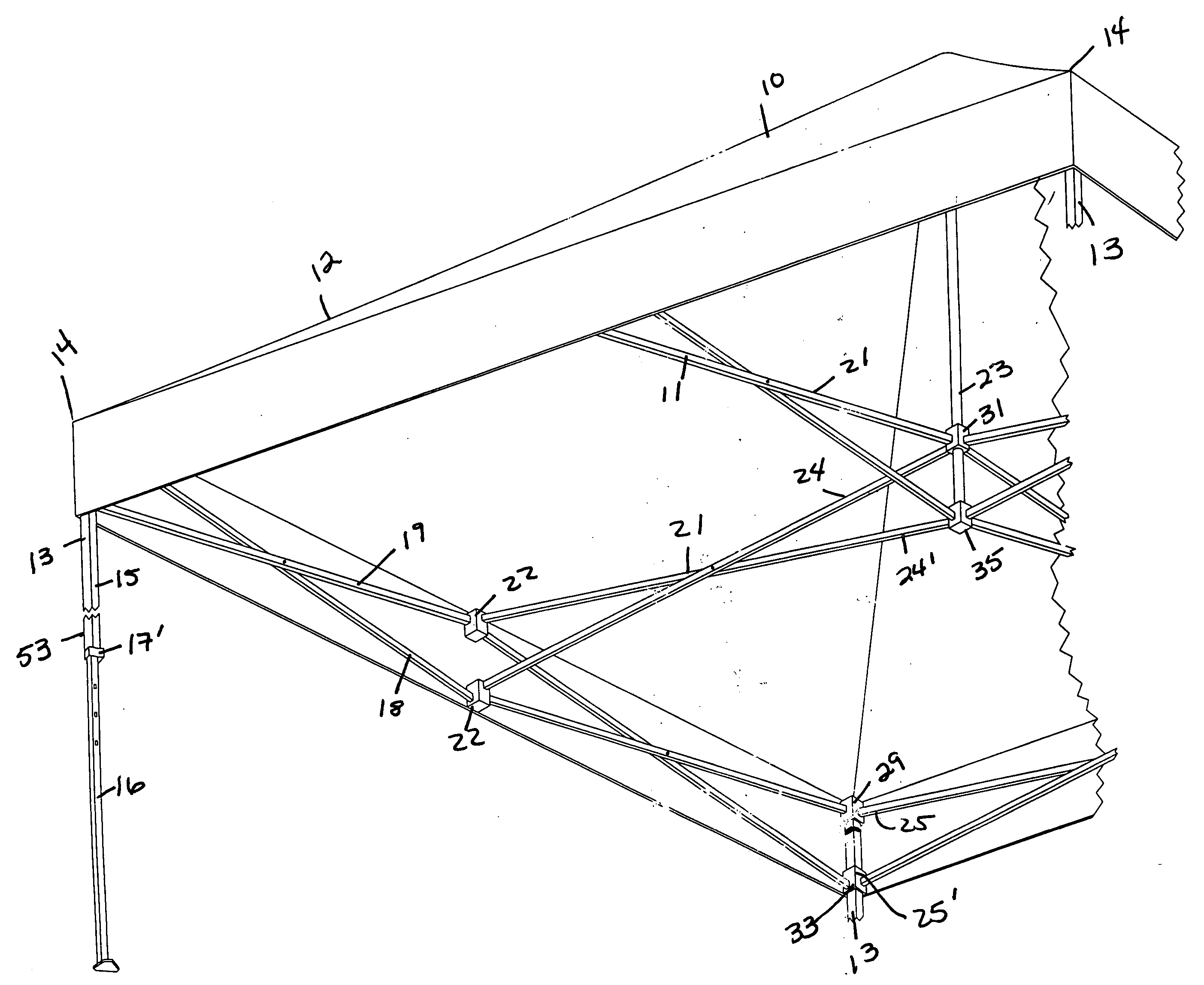
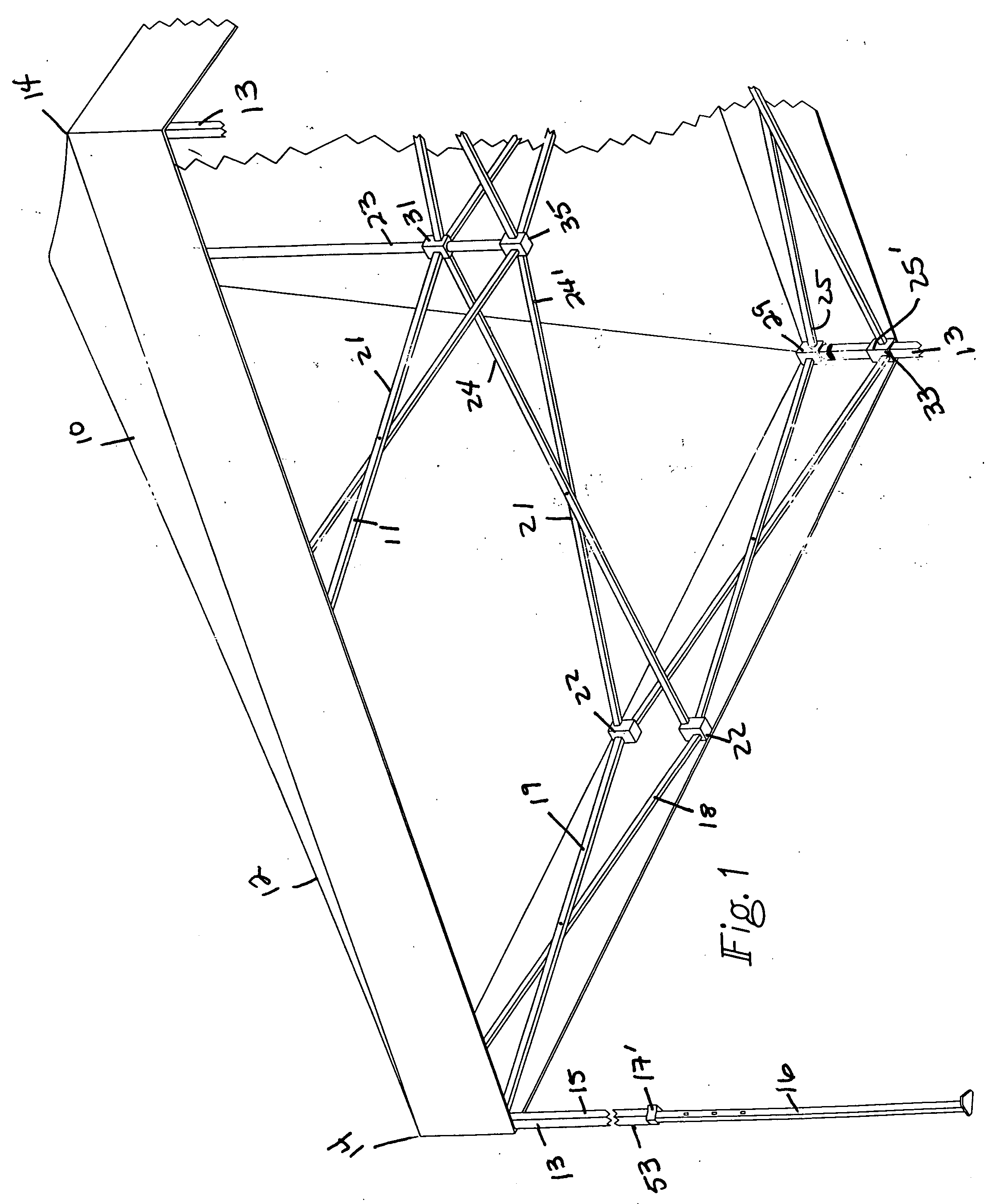
[0023] Referring in more detail to the drawings, there is shown in FIG. 1 a form of shelter 10 broadly comprised of a collapsible frame assembly 11 including a canopy 12 typically of canvas composition and of a generally polygonal configuration with four corners 14 (three shown). The frame 11 has four vertical support legs 13 at spaced peripheral intervals beneath the canopy 12. Each vertical support leg 13 has upper and lower telescoping members 15 and 16 which are of square cross-section and provided with an adjustable locking member 17 to regulate the length of extension or height of the canopy. The adjustable locking member 17 will be discussed in more detail at a later point. The frame 11 has outer peripheral truss sections 18 made up of two pair of scissors-like pivotal arm members 19 in end-to-end relation to one another between adjacent corners of the frame with connectors or truss mounts 22 between adjoining ends of the arm members 19; and radial truss sections 21 extending...


PUM


Abstract

A collapsible shelter of the type having a canopy and a frame, the frame having mounting members with a stabilizer, reduced friction pivot shafts and an adjustable locking member having a spring providing for easy adjustment of the height and breadth of the canopy.

Description

BACKGROUND AND FIELD OF INVENTION [0001] This invention relates to shelters; and more particularly relates to a collapsible shelter which has novel and improved mounting supports providing added stability as well as a novel push pin assembly on side support legs which provides for ease of use. [0002] Shelter assemblies having a canopy, collapsible frame with corner legs and a center support are in widespread use. The trend now has been to construct collapsible shelters that are lightweight and can be assembled quickly by a single person. A problem confronting users of collapsible shelters is that the lightweight design is not always as stable as its heavier counterparts. The truss sections are subject to buckling as well as overextension or misalignment of the arm members mounted on the corner legs and center support. Further, collapsible shelters have incorporated pull pin technology such as in U.S. Pat. No. 6,508,262 to Takiyama or the pull pin assembly in U.S. Pat. No. 6,575,646 ...

Claims


Application Information

Patent Timeline
IPC IPC(8): E04H15/50E04H15/38
CPCE04H15/50Y10T403/342Y10T403/32483Y10T403/44
Inventor MALLOOKIS, STEVEN E.KO, CHAO-SHUN
Owner GO PAPA LLLP
Why Eureka
Try Eureka