
Drive device for electrically movable vehicles and electric wheelchair having same

a technology of electric wheelchairs and drive devices, which is applied in the direction of electric propulsion mounting, wheelchairs/patient conveyances, transportation and packaging, etc., can solve the problems of increased size and weight of wheelchairs, inconvenient indoor movement and short turning radius of wheelchairs, and power interruption of motors to drive wheels, so as to improve safety

Inactive Publication Date: 2006-05-11
SANYO ELECTRIC CO LTD
View PDF26 Cites 16 Cited by
  • Summary
  • Abstract
  • Description
  • Claims
  • Application Information

AI Technical Summary

Benefits of technology

[0008] A first object of the present invention is to provide an electric vehicle drive device which can be reduced in size and in the diameter of the drive wheel and which is improved in braking performance, and an electric wheelchair comprising the drive device.
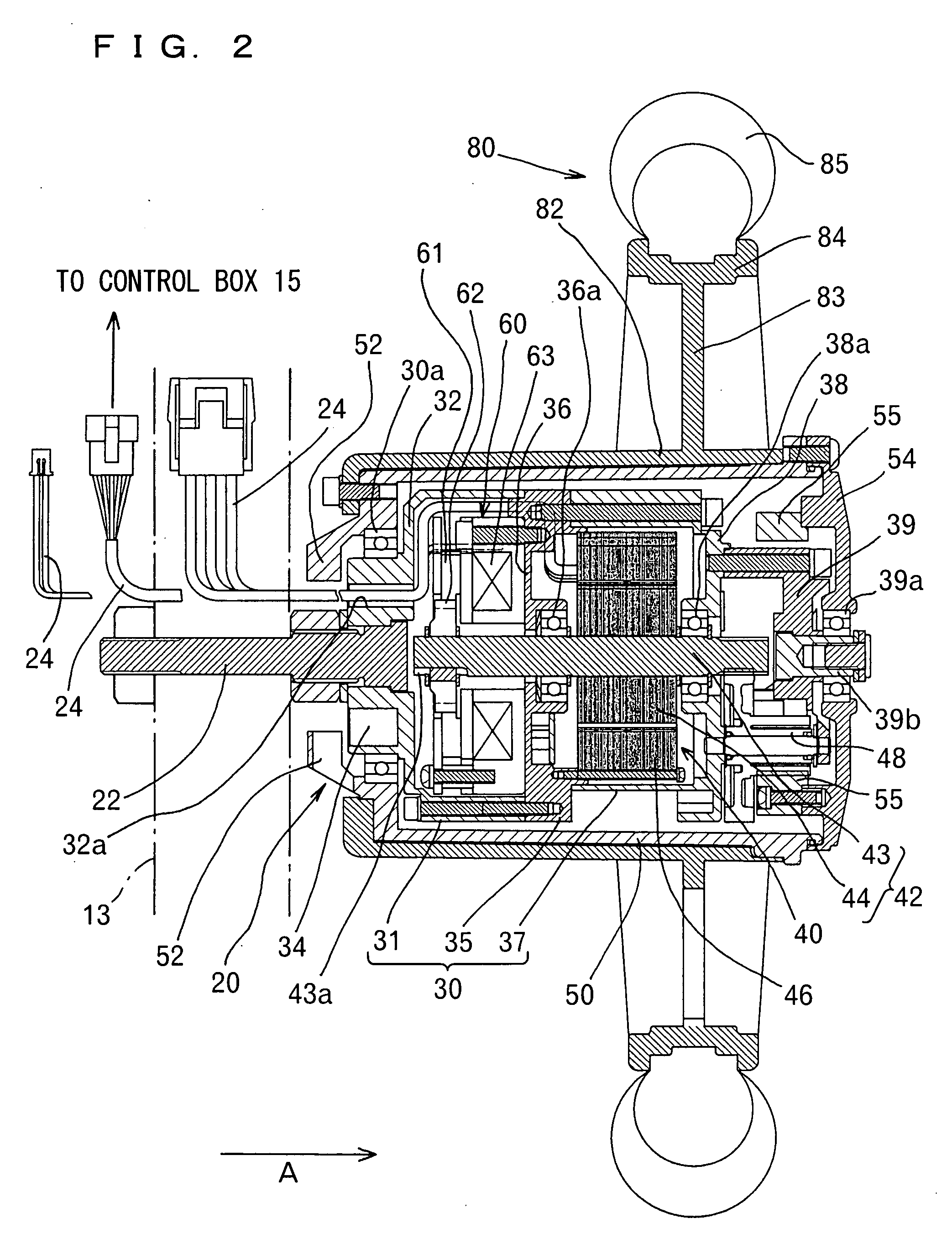
[0011] With the drive device of the present invention, the axle supporting the drive device is in alignment with the rotating shaft of the motor, so that the drive device itself can be reduced in size, and the drive wheel to be provided around the outer periphery of the drive device can be smaller in diameter. Since the rotating shaft and the drive wheel are rotatable about the same center, unevenness of the reaction force is avoidable, permitting the axle aligned with the rotating shaft to receive the reaction force uniformly.
[0013] With the drive device of the present invention, the axle supporting the drive device is in alignment with the rotating shaft of the motor, so that the drive device itself can be reduced in size, and the drive wheel to be provided around the outer periphery of the drive device can be smaller in diameter. Since the rotating shaft and the drive wheel are rotatable about the same center, unevenness of the reaction force is avoidable, permitting the axle aligned with the rotating shaft to receive the reaction force uniformly.
[0014] With the brake disposed closer to the axle than the motor, the wiring for the electromagnetic brake can be shortened, and the drive device is simplified in interior construction and made easy to maintain.
[0022] Accordingly, even if the clutch mechanism is disengaged when the vehicle is held at rest on a downward slope or the like by the brake, the dynamic braking force or the like of the motor obviates the likelihood that the vehicle will become accelerated over a given speed, hence improved safety.

Problems solved by technology

The increase in the wheel diameter is likely to make it difficult for the user to move from the wheelchair, for example, to a bed, renders the wheelchair itself greater in size and weight and therefore makes the wheelchair inconvenient to move indoors and to drive with a short turning radius.
When the clutch is disengaged, the transmission of power from the motor to the drive wheel is therefore interrupted, and the motor fails to deliver its braking force to the drive wheel.

Method used


Image

  • Drive device for electrically movable vehicles and electric wheelchair having same
  • Drive device for electrically movable vehicles and electric wheelchair having same
  • Drive device for electrically movable vehicles and electric wheelchair having same

Examples


first embodiment

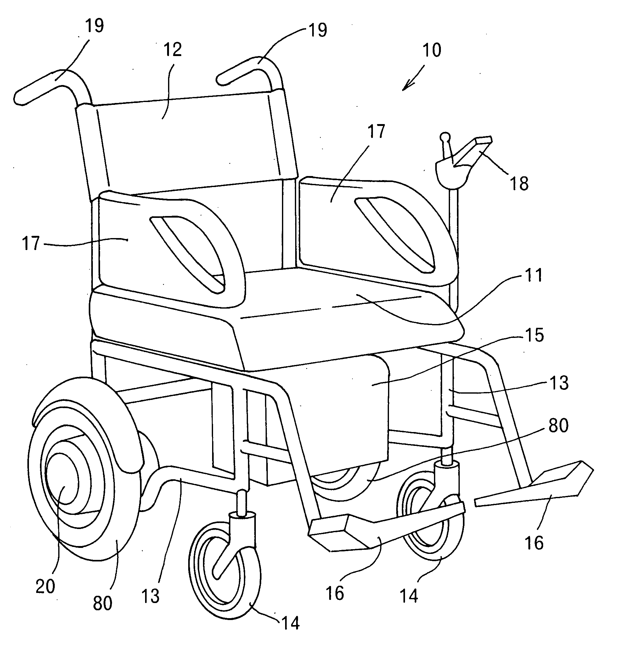
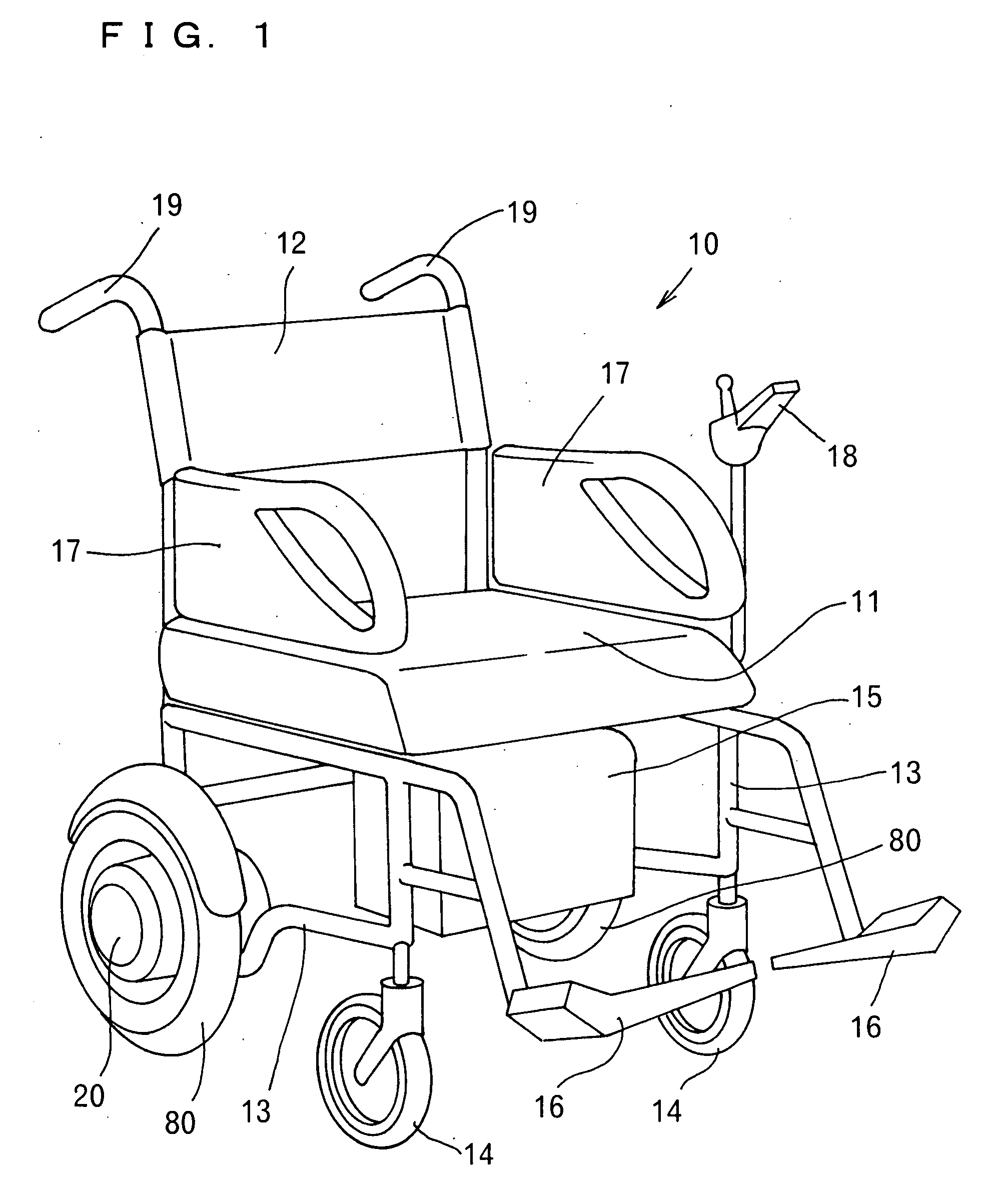
[0034] This embodiment will be described below with reference to an electric wheelchair 10 serving as an electric vehicle and to be used by elderly or disabled persons, whereas the present invention is applicable also to other electric vehicles such as golf carts or small vehicles.

[0035]FIG. 1 is a perspective view of the electric wheelchair 10, which comprises a pair of drive devices 20, 20 of the invention provided for respective left and right drive wheels 80, 80. The wheelchair 10 comprises a seat 11 for the user to sit in, and a backrest 12. Extending downward from the seat 11 is a frame 13 provided with the left and right drive devices 20, 20 and drive wheels 80, 80. Positioned to the front of the respective drive wheels 80, 80 are auxiliary wheels 14, 14 supported by the frame 13 and having a smaller diameter than the drive wheels 80, 80.

[0036] Disposed under the seat 11 is a control box 15 having a battery, power controller and other control means. Footrest pedals 16, 16 a...

second embodiment

[0064] According to this embodiment, a drive device 20 comprises a clutch mechanism 70 for connecting the rotating shaft 43 to the electromagnetic brake 60 or disconnecting the shaft 43 from the brake 60. Throughout the drawings showing the first and second embodiments, like parts are designated by like reference numerals.

[0065]FIG. 5 is a perspective view of an electric wheelchair 10 wherein the drive device 20 of the second embodiment is provided for each of left and right drive wheels 80, 80. Handles 19, 19 for the help extend rearward from the upper portion of a backrest 12. Each of the handles 19 is provided with a clutch controller 77 (to be described later) for engaging or disengaging the clutch mechanism 70.

[0066] The control device 18 can be, for example, of the joystick type for varying the speed of the wheelchair 10 and turning the wheelchair 10. The wheelchair 10 can be advanced or moved backward by inclining the joystick forward or backward. The wheelchair 10 can be t...


PUM


Abstract

The invention provides a drive device for electric vehicles which is small-sized, improved in heat radiating characteristics and adapted for use with a drive wheel of reduced diameter, and an electric wheelchair comprising the drive device. The drive device is provided on the inner periphery of each of left and right drive wheels 80, 80 of the electric vehicle and comprises a casing 30 supported at one end thereof by an axle 22 on the electric vehicle, a motor 40 housed in the casing 30 and having a rotating shaft 43 aligned with the axle 22, and a housing 50 rotatably fitted around the casing 30 and rotatable by the rotation of the motor 40. The drive wheel 80 is provided around the outer periphery of the housing 50 and rotatable therewith.

Description

FIELD OF THE INVENTION [0001] The present invention relates to drive devices for use in electrically movable vehicles, i.e., electric vehicles, such as electric wheelchairs, and more particularly to electric vehicle drive devices having a drive wheel around the device and to be supported only at one end thereof by an electric vehicle. BACKGROUND OF THE INVENTION [0002] Electric vehicles such as electric wheelchairs include those having a drive device for driving each of left and right drive wheels individually with a motor (as disclosed, for example, in Japanese Patent No. 3432977, JP-A No. 9-296829 and JP-A No. 2000-70309). [0003] The drive device disclosed in Japanese Patent No. 3432977 comprises a hollow hub case rotatably mounted on an axle at the center of the drive wheel, a metal closure covering an opening of the hub case, a case having enclosed therein a motor for the drive wheel and an electromagnetic brake, fixed to the wall of the hub case opposite to the closure and posi...

Claims


Application Information

Patent Timeline
IPC IPC(8): B60K1/00
CPCA61G5/045A61G2203/14B62B5/04H02K7/116H02K7/14Y02T10/641A61G5/1032Y02T10/64
Inventor AKAGI, TAKAYOSHINORO, TAKUYATOMOSHIGE, KAZUHIRO
Owner SANYO ELECTRIC CO LTD
Learn More