Method and apparatus for thermal characterization under non-uniform heat load

Inactive Publication Date: 2006-05-11
GLOBALFOUNDRIES INC
View PDF18 Cites 19 Cited by
  • Summary
  • Abstract
  • Description
  • Claims
  • Application Information

AI Technical Summary

Benefits of technology

[0019] In yet another embodiment, the cooling device is coated with a blackbody coating to help absorb the laser beam and increase the emissivity of the cooling device, which improves the temperature measurements. In other embodiments, the test ch

Problems solved by technology

Almost all the electrical energy consumed by the chip package is released into the surroundings as heat, which thus places an enormous burden on the cooling device and cooling package.
This phenomenon can adversely affect the thermal performance of the cooling device, which is typically designed to function and tested under a more spatially uniform heat load.
Specifically, degrada

Method used


Image

  • Method and apparatus for thermal characterization under non-uniform heat load
  • Method and apparatus for thermal characterization under non-uniform heat load
  • Method and apparatus for thermal characterization under non-uniform heat load

Examples


Embodiment Construction

[0037] It should be understood that these embodiments are only examples of the many advantageous uses of the innovative teachings herein. In general, statements made in the specification of the present application do not necessarily limit any of the various claimed inventions. Moreover, some statements may apply to some inventive features but not to others. In general, unless otherwise indicated, singular elements may be in the plural and vice versa with no loss of generality. In the drawings, like numerals refer to like parts through several views.

[0038] While the specification concludes with claims defining the features of the invention that are regarded as novel, it is believed that the invention will be better understood from a consideration of the following description in conjunction with the drawing figures, in which like reference numerals are carried forward.

[0039] Electronic Device

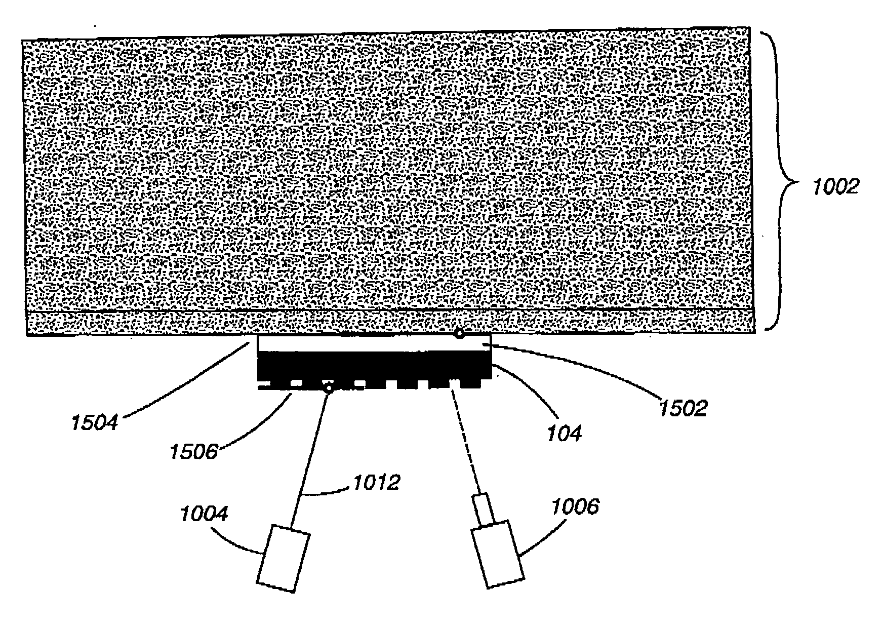
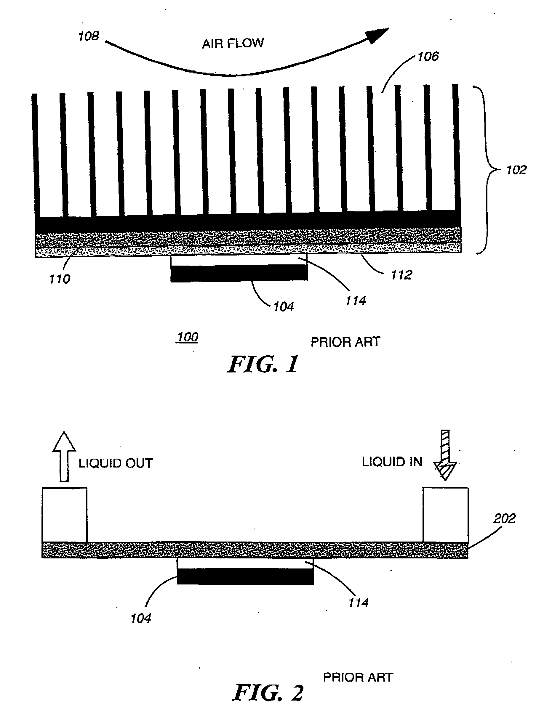
[0040]FIG. 7 shows a Prior Art electronic device 104 (previously shown in FIG. 1), having a...


PUM


Abstract

A method and apparatus for real-time thermal characterization of a fully operating cooling device (1002). A heat source (1004) is applied to one or more areas on a cooling device (1002) to produce non-uniform heating of the cooling device. Infrared (IR) temperature imaging (1006) detects and measures the thermal distribution of the heat source (1004) on the cooling device (1002) to develop a thermal characterization of the cooling device (1002).

Description

BACKGROUND OF THE INVENTION [0001] 1. Field of the Invention [0002] This invention relates in general to characterizing cooling devices and cooling packages for electronic components and more particularly, to an apparatus and method of thermal characterization of a cooling device under non-uniform heat loads. [0003] 2. Description of the Related Art [0004] Microprocessor performance has improved significantly over the last decade. To effect this improvement in device performance, the density of circuitry has increased. More and more transistors are fabricated in smaller chip size. This has in turn, led to an exponential rise in package power densities, and this trend is expected to continue into the foreseeable future. Almost all the electrical energy consumed by the chip package is released into the surroundings as heat, which thus places an enormous burden on the cooling device and cooling package. [0005] Existing cooling technologies typically utilize air or water to carry the he...

Claims


Application Information

Patent Timeline
IPC IPC(8): H01L23/34
CPCH01L23/34H01L2924/0002H01L2924/00
Inventor HAMANN, HENDRIK F.IYENGAR, MADHUSUDAN K.LACEY, JAMES A.SCHMIDT, ROGER R.
Owner GLOBALFOUNDRIES INC
Why Eureka
Try Eureka