Image display system

Inactive Publication Date: 2006-05-11
DENSO CORP
View PDF7 Cites 35 Cited by
  • Summary
  • Abstract
  • Description
  • Claims
  • Application Information

AI Technical Summary

Benefits of technology

[0010] Accordingly, the display content to be displayed next is determined by the display control unit based on the obtained manipulation signal and the stored correspondence. Therefore, the switch indicator to be selected next is not determined based on relative positions of the switch indicators on the display screen. For example, it is less likely that a switch indicator in a first screen section of the display screen will be selected based on the relative positions of the switch indicators during operati

Problems solved by technology

Therefore, the switch indicator on the list screen may be accidentally selected during operation on the map screen.
On

Method used


Image

  • Image display system
  • Image display system
  • Image display system

Examples


first embodiment

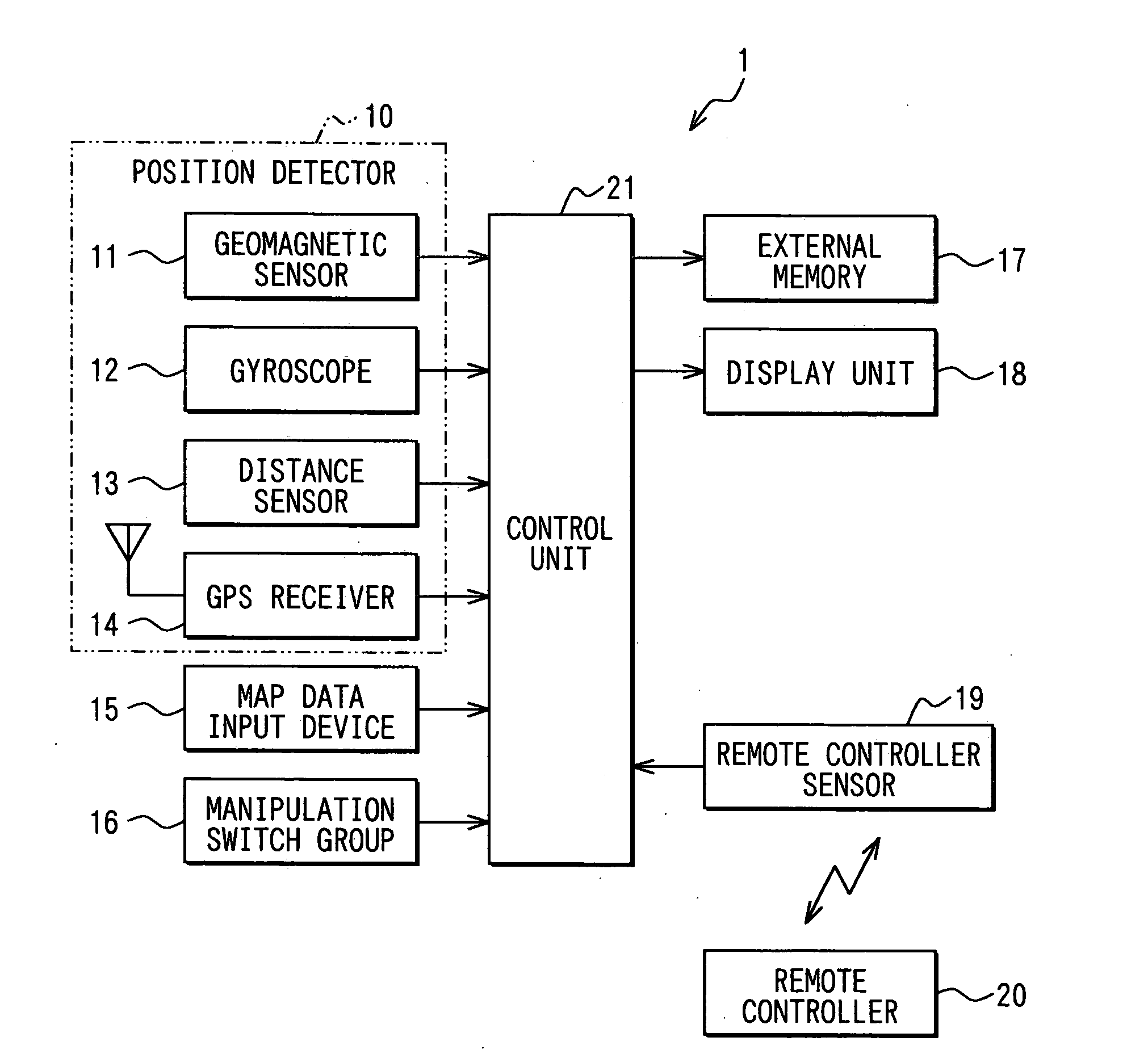
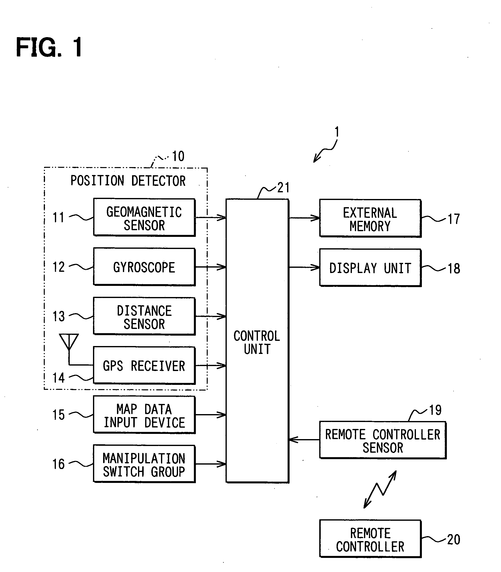
[0025] An image display system of the first embodiment is for example applied to a navigation system for a vehicle. As shown in FIG. 1, a navigation system 1 has a position detector 10, a map data input device 15, a group of manipulation switches 16, an external memory 17, a display unit 18, a remote controller sensor 19, and a control Unit 21. The preceding devices are connected to the control unit 21.

[0026] The position detector 10 includes a geomagnetic sensor 11, a gyroscope 12, a distance sensor 13 and a GPS (Global Positioning System) receiver 14 for detecting a current position of a vehicle based on radio waves from satellites. Each device 11 to 14 has a different characteristic and detection accuracy, so respective errors are adjusted through combining the devices 11 to 14 to obtain high position detection accuracy.

[0027] The map data input device 15 includes a storage medium and inputs various data such as map data, landmark data, and map matching data for improving accur...

second embodiment

[0070] In the second embodiment, hardware of the image display apparatus is the same as that of the first embodiment, but processing executed by the control unit 21 is different from that of the first embodiment. Hereafter, different processes are mainly described and like processes are not repeated.

[0071]FIGS. 6A and 6B show examples of display images displayed on the display screen. In FIG. 6A, switch indicators A1, B2, C3 are displayed in the from of list. When the listed switch indicators A1, B2, C3 shown in FIG. 6A are scrolled down one row, switch indicators Z9, A1, B2 are displayed, as shown in FIG. 6B.

[0072] In the image display apparatus 1 of the second embodiment, correspondences between the manipulation signal and an instruction to scroll the listed switch indicators are stored in the external memory 17, for the respective switch indicators. Specifically, correspondences between the manipulation signal according to manipulation of the direction keys 20a and the next dis...

third embodiment

[0087] In the third embodiment, hardware of the image display apparatus 1 is similar to that of the first embodiment, but processing executed by the control unit 21 is different from that of the first embodiment. Hereafter, different processes are mainly described and like processes are not repeated.

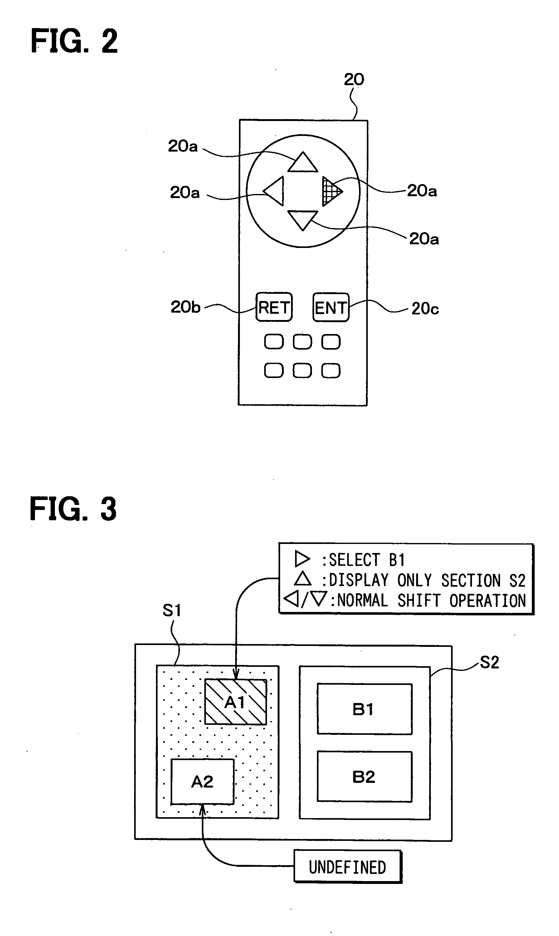
[0088] In the image display apparatus 1 of the third embodiment, the map screen (section S1) and the list screen (section S2) are displayed side by side on the display screen of the display unit 18, as shown in FIGS. 8A to 8C. Further, regarding the map screen S1, a mode is selected between a current position display mode in which the current position is indicated in a map and a map scroll mode in which the map is scrolled in accordance with the manipulation signal.

[0089] In FIG. 8A, a current position display screen is displayed on the left side of the display screen and a list screen is displayed on the right side. In FIG. 8B, a map scroll screen is displayed on the left side and the...


PUM


Abstract

In an image display system, a manipulation signal obtaining unit obtains a manipulation signal in accordance with manipulation of manipulation switches. A display control unit controls to display a plurality of switch indicators, which are selectable based on the manipulation signal, on a display screen. A storing unit stores correspondences between the manipulation signal and a display content to be displayed next on the display screen, for the respective switch indicators. The display control unit determines the display content to be displayed next based on the manipulation signal obtained by the manipulation signal obtaining unit and the correspondence stored in the storing unit, and displays the determined display content on the display screen.

Description

CROSS REFERENCE TO RELATED APPLICATION [0001] This application is based on Japanese Patent Application No. 2004-326525 filed on Nov. 10, 2004, the disclosure of which is incorporated herein by reference. FIELD OF THE INVENTION [0002] The present invention relates to an image display system that selects switch indicators, which are selectable based on signals sent from manipulation switches such as direction keys, an enter key, and controls processing, and the system is for example used for a navigation system. BACKGROUND OF THE INVENTION [0003] In an image display system, it is known to display information groups consisting of a plurality of sub-information and a pointer for pointing the sub information on a display screen. In accordance with operation of a direction key by a user, the pointer is shifted in a designated direction. Also, pointer movable marks indicative of directions to which the pointer can be shifted with respect to the information group are displayed on the displa...

Claims


Application Information

Patent Timeline
IPC IPC(8): G09G5/00G06F3/048G06F3/0484G06F3/0485G06F3/0489
CPCG06F3/0482
Inventor MIZUNO, TOSHINORI
Owner DENSO CORP
Why Eureka
Try Eureka