Sensing display

a display and sensing technology, applied in the field of information displays, can solve the problems of affecting the use of the frame, the increase of the parts count, weight and cost of the device created by the frame, and the presence of redundant components

Active Publication Date: 2006-05-11
GLOBAL OLED TECH
View PDF14 Cites 30 Cited by
  • Summary
  • Abstract
  • Description
  • Claims
  • Application Information

AI Technical Summary

Benefits of technology

[0009] In one aspect of the invention, the display comprises a substrate, an array of individually controllable image-forming elements arranged on the substrate; and a support located proximate to the substrate. The support has an arrangement of light paths formed therein to transmit light from a light source to a light sensor. The light paths are arranged in an area that is, at least in part, co-extensive with the array. The support is elastically deformable so that an application of force to the support causes the light paths to deform in a manner that reduces the portion of light passing through light paths that are elastically deformed by the application of force.

Problems solved by technology

These prior-art arrangements combining touch screens and displays suffer from a variety of drawbacks.
These drawbacks include, but are not limited, to the increased parts count, weight, and cost of the device created by the use of the frame and the presence of redundant components in the display and touch screen.
Further, there is a risk that the light sources or light receivers can become blocked or contaminated by environmental matter, and thus yield false results.
Further, such light guides are capable only of detecting whether a light path has been fully interrupted and are not capable of sensing interruptions in a way that allows for a variable input to be made.

Method used


Image

  • Sensing display
  • Sensing display
  • Sensing display

Examples


Embodiment Construction

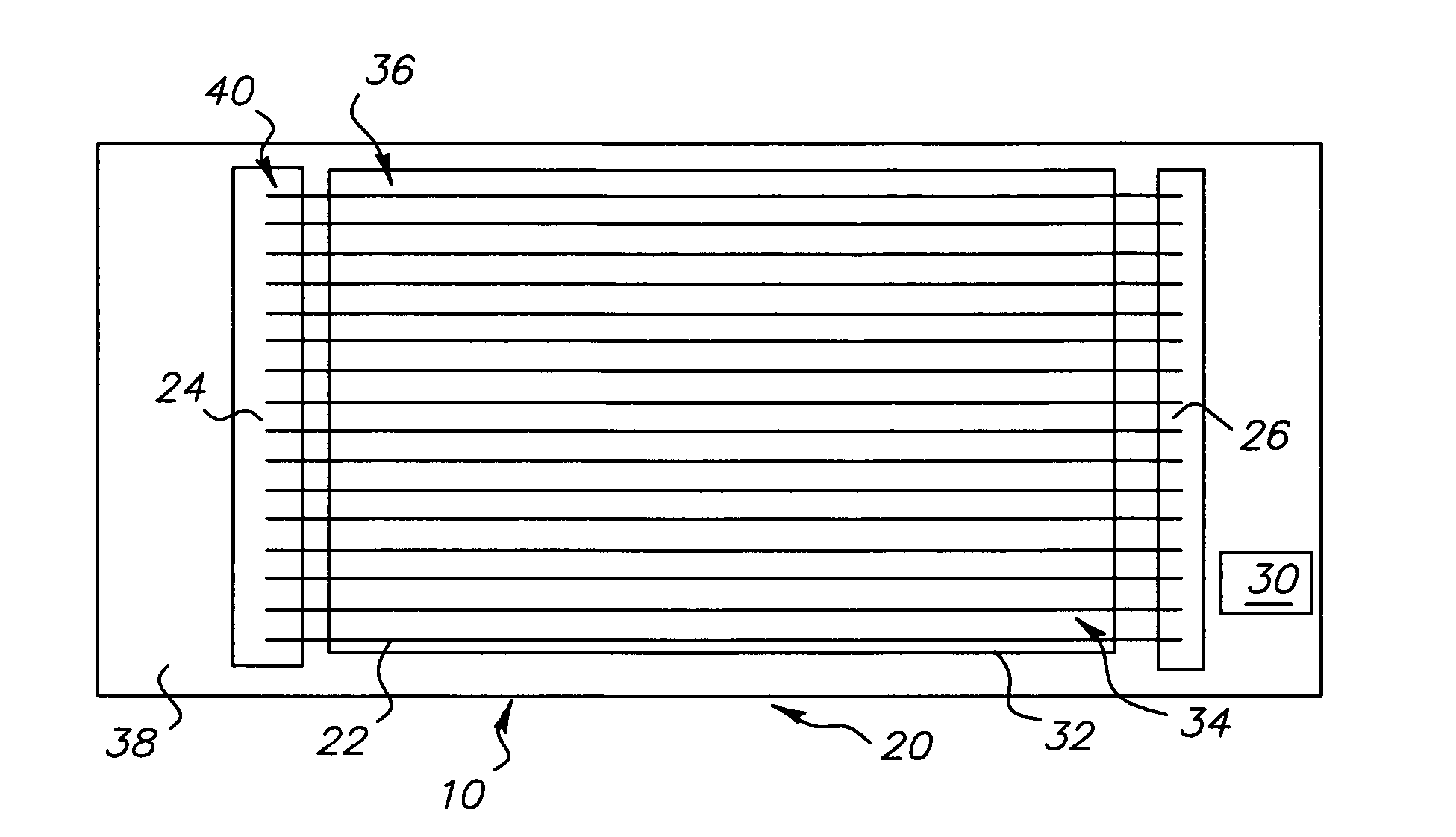
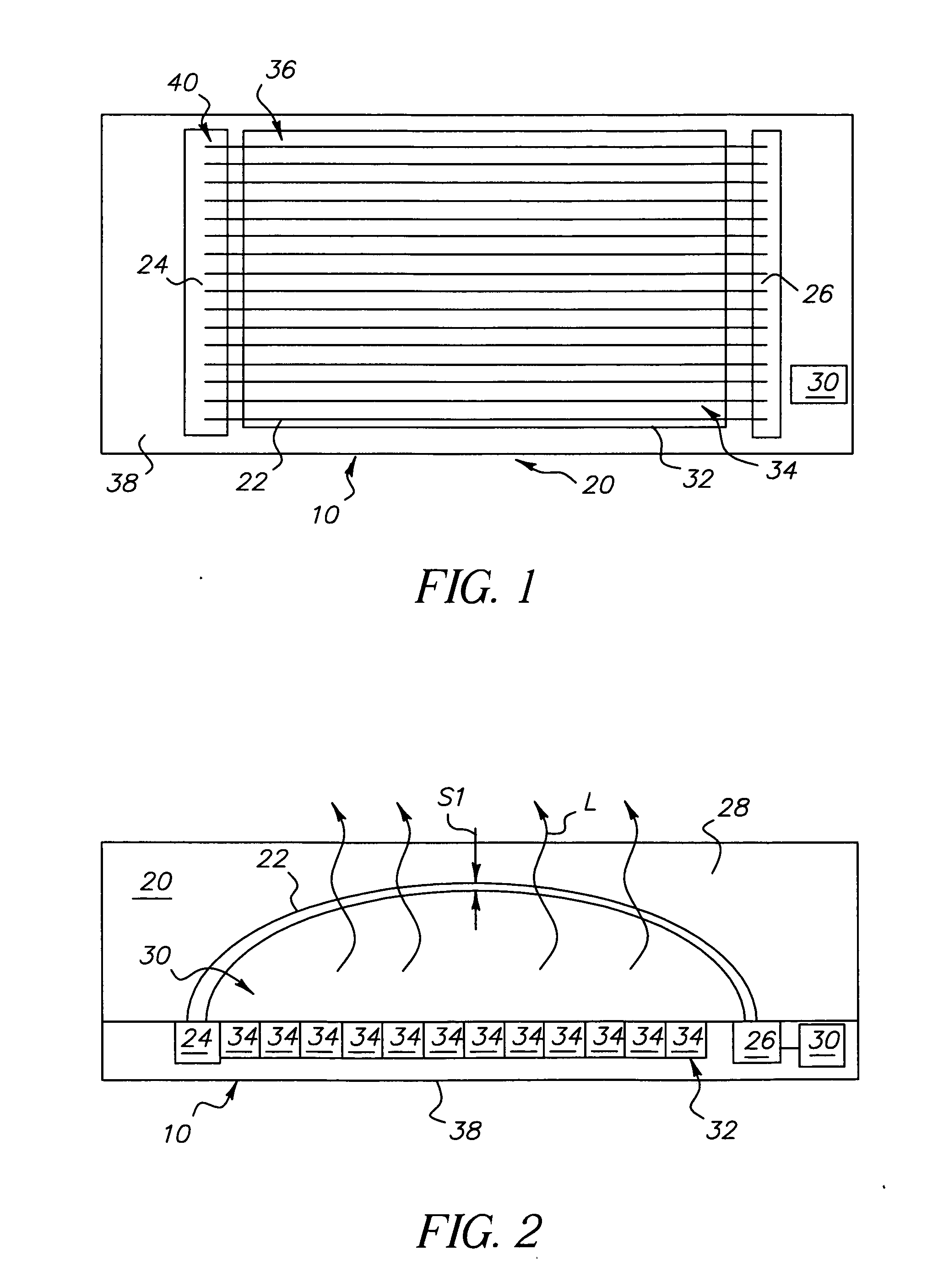
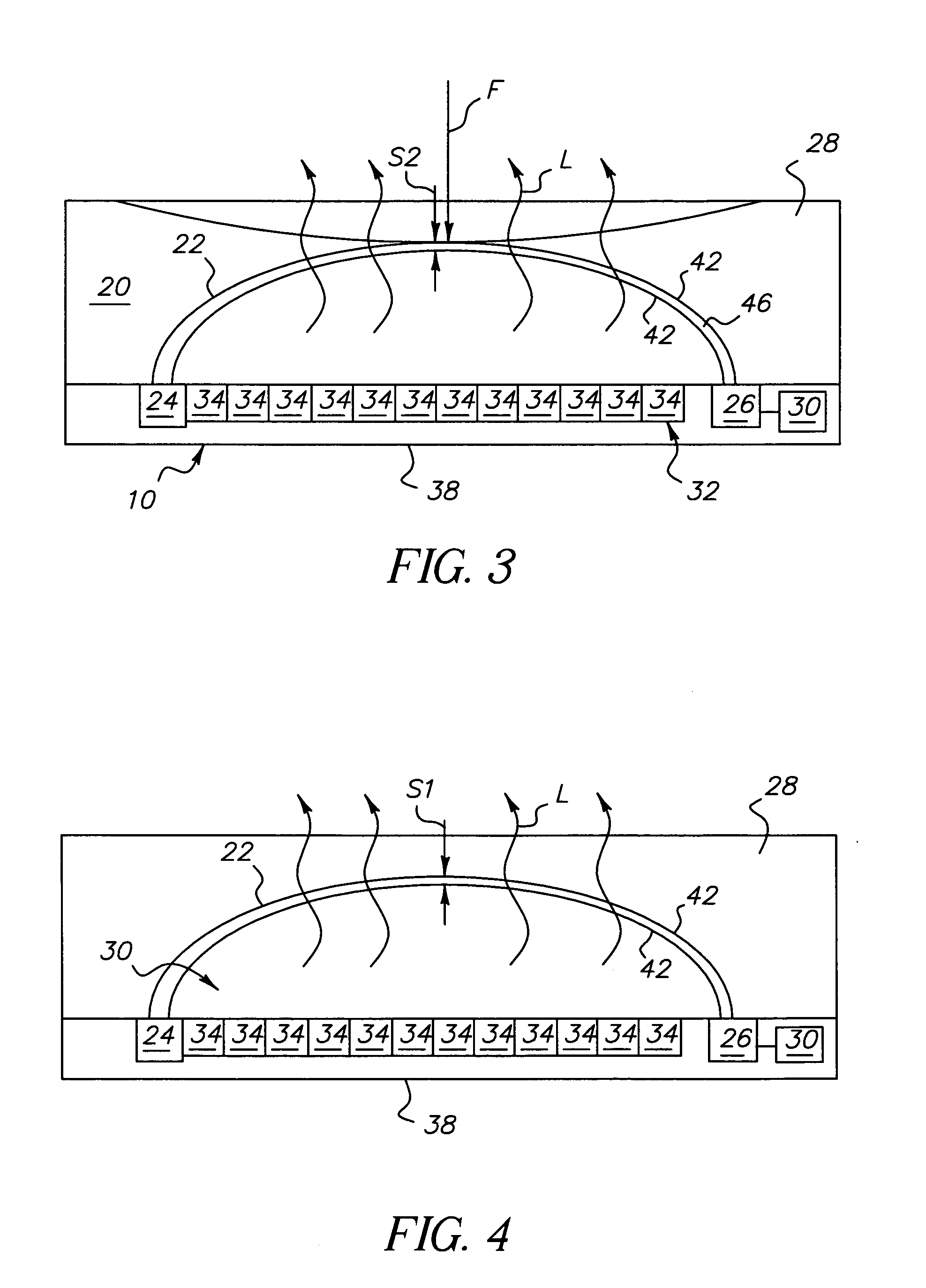
[0045]FIG. 1 shows a top view and FIGS. 2 and 3 show sectional side views of one embodiment of a sensing display 10 of the invention. In this embodiment, sensing display 10 comprises a support 20 having an arrangement of light paths 22 formed therein to transmit light from a light source 24 provided proximate to support 20 to a light sensor 26 also provided proximate to support 20. Support 20 is formed from a support material 28. Support material 28 is elastically deformable from a relaxed state shown on FIG. 2 to a range of elastically deformed states, one example of which is shown in FIG. 3.

[0046] As is shown in FIGS. 2 and 3, the application of a force F to support 20 causes support material 28 to elastically deform in an area in which force is applied. Light paths 22 are provided so that a force-induced deformation of support material 28 causes deformation of light paths 22 such that the proportion of light that is transmitted from light source 24 to light sensor 26 by the affe...


PUM


Abstract

A display and method for making the same are provided that can sense a force applied thereto. The display comprises a substrate, an array of individually controllable image-forming elements arranged on the substrate; and a support located proximate to the substrate. The support has an arrangement of light paths formed therein to transmit light from a light source to a light sensor. The light paths are arranged in an area that is, at least in part, co-extensive with the array. The support is elastically deformable so that an application of force to the support causes the light paths to deform in a manner that reduces the portion of light passing through light paths elastically deformed by the application of force.

Description

FIELD OF THE INVENTION [0001] This invention relates generally to information displays and, more particularly, to an information display with an integrated touch screen capability. BACKGROUND OF THE INVENTION [0002] Modern electronic devices provide an increasing amount of functionality with a decreasing size. By continually integrating more and more capabilities within electronic devices, costs are reduced and reliability increased. Touch screens are frequently used in combination with conventional soft displays such as cathode ray tubes (CRTs), liquid crystal displays (LCDs), plasma displays and electroluminescent displays. The touch screens are manufactured as separate devices and mechanically mated to the viewing surfaces of the displays. [0003] Several examples of such touch screens are known, U.S. Patent Publication No. 2002 / 01759001A1 by Armstrong, published Nov. 28, 2002, describes a touch system for use with an information display system including a frame defining an openin...

Claims


Application Information

Patent Timeline
Patent Type & Authority Applications(United States)
IPC IPC(8): G09G5/00
CPCG06F3/0412G06F3/0421
Inventor COK, RONALD S.
Owner GLOBAL OLED TECH
Why Eureka
Try Eureka