
Method and device for the detection and track of targets in high clutter

a high-clutter, detection and tracking technology, applied in the field of radar systems, can solve the problem of not having a suitable method and device for tracking a target in clutter, and achieve the effect of effective detection and tracking a target, and effective filtering of clutter

Inactive Publication Date: 2006-12-26
US OF AMER REPT BY SEC OF THE ARMY
View PDF18 Cites 29 Cited by
  • Summary
  • Abstract
  • Description
  • Claims
  • Application Information

AI Technical Summary

Benefits of technology

Effectively filters clutter from radar signals, allowing for accurate tracking of targets by isolating the target signal from clutter, improving signal-to-clutter ratio and enhancing detection capabilities in high-clutter environments.

Problems solved by technology

However, to date, no suitable method and device of tracking a target in clutter is available which effectively filters clutter from a reflected radar signal.

Method used


Image

  • Method and device for the detection and track of targets in high clutter
  • Method and device for the detection and track of targets in high clutter
  • Method and device for the detection and track of targets in high clutter

Examples


example

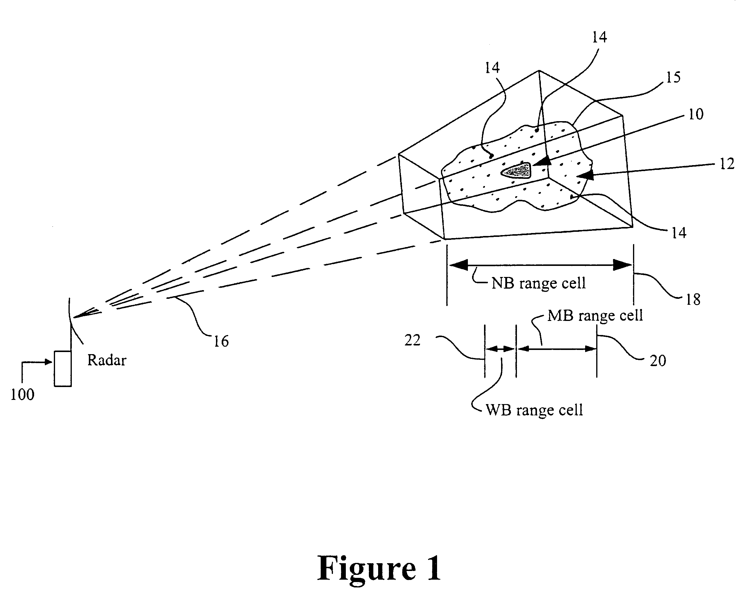
[0031]It is desired to detect and track a centroid of a clutter cloud 12 having ten million dipoles of chaff occupying a one-kilometer range extent. Since there is a normal distribution of chaff dipoles, approximately 67% of the chaff dipoles occupy 333 meters of range extent. Using a nominal PRF of 10 Hz and a pulse length of eight milliseconds, NB track of the cloud can be initiated. The cross section (C / S) of each dipole of chaff may be calculated from the formula:

Drcs=0.18Nλ2

In this case, one NB range bin contains approximately:

Drcs=0.18(670,000)(0.03)2

Drcs=108.54 or approximately 20 dBsm

Where: N=(0.67)(1,000,000), λ=0.03m (nominal X-band radar wavelength) and Drcs is the combined radar cross section of the dipoles that reside in the NB resolution cell.

Given that for an eight milliseconds pulse width the single pulse minimum rms track error (Fe) is about 8 Hz, at X-band, a single pulse velocity error (Ve) of 0.12 meters per second (m / s) results (Ve=[Fe*λ] / 2). Accordingly, a wi...

embodiment

OPTIONAL EMBODIMENT

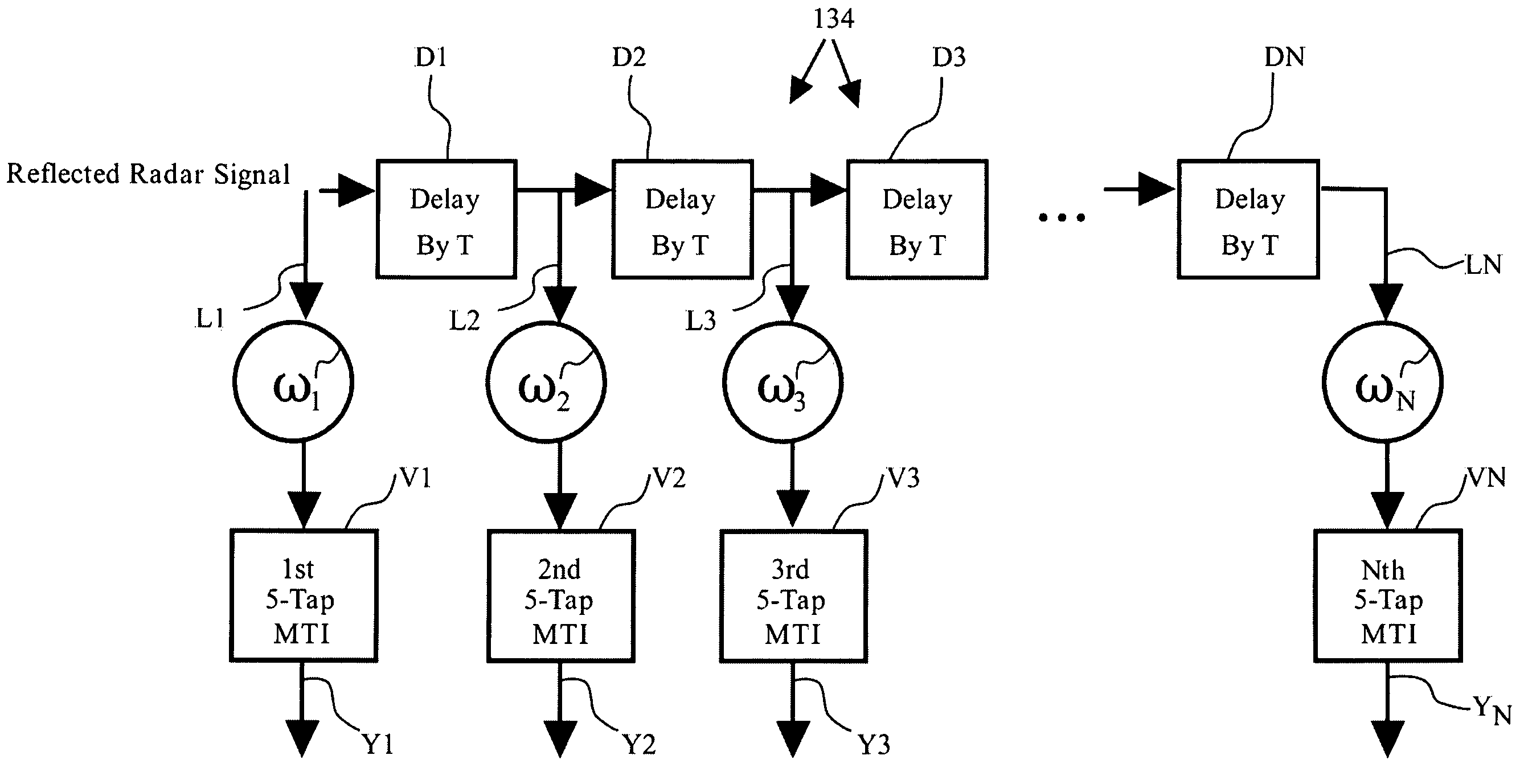
[0034]Referring now to FIG. 6, an optional embodiment of a method and device for processing a reflected radar signal in accordance with the present invention is illustrated generally at 200. In this particular embodiment, integration at 202 is carried out on a reflected radar signal prior to filtering the signal in a manner which may be similar to the filtering arrangement described in the embodiment above and shown generally at 204. The integration 202 preferably comprises a sixteen pulse sliding window coherent integration which is known to one of ordinary skill in the art and further details of this technique may be found in the discussions of prediction integration in the book “Introduction to Radar Systems” previously incorporated herein by reference. It will be appreciated that the sixteen pulse integrator provides an additional boost in S / C which may be necessary to further increase the S / C where clutter is extensive, particularly where a single pulse S / C i...


PUM


Abstract

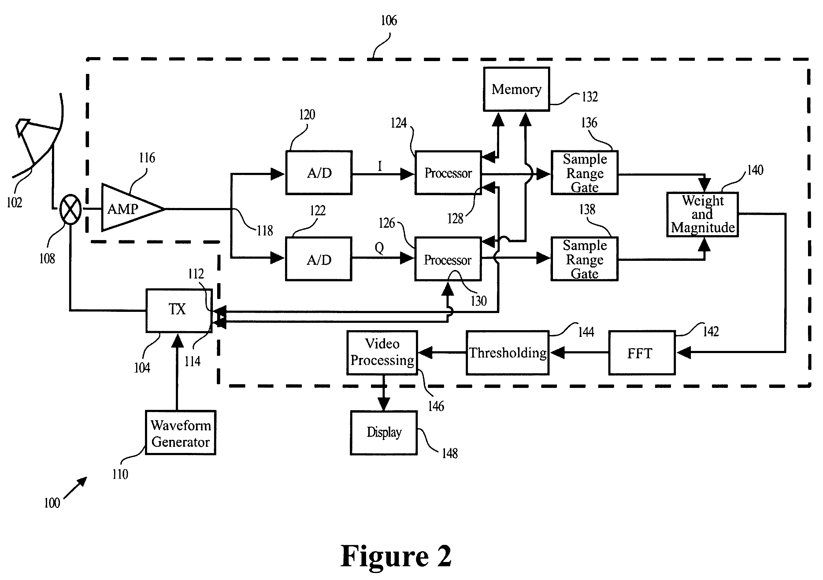
A method for discriminating and tracking a target in a clutter cloud includes transmitting a radar signal at a signal bandwidth to: identify a range extent of a clutter cloud; determine a centroid and a velocity growth rate of the clutter cloud; and identify a direction of movement of the centroid of the clutter cloud. The method may also include locking a another radar signal having a greater signal bandwidth onto the centroid of the clutter cloud whereby the centroid is tracked within one radar range resolution bin; providing a delay line that includes at least two Doppler filters and is configured to cover a Doppler frequency range corresponding to a velocity growth rate of the clutter cloud; and processing a reflected radar signal corresponding to the greater signal bandwidth. The processing of the reflected radar signal may comprise passing the reflected radar signal through the delay line to mitigate a portion of the reflected signal that is reflected by the clutter cloud. A system and apparatus for performing the method is also provided.

Description

CROSS REFERENCE TO RELATED APPLICATIONS[0001]This is a division of U.S. patent application Ser. No. 10 / 346,157, entitled “Method and Device for the Detection and Track of Targets in High Clutter”, filed Jan. 16, 2003, now U.S. Pat. No. 6,809,682.BACKGROUND OF THE INVENTION[0002]1. Field of the Invention[0003]The present invention relates to radar systems and, more particularly, to Doppler radar systems for tracking targets in high clutter.[0004]2. Related Art[0005]Numerous Doppler radar systems including Doppler processing techniques are available. For example, U.S. Pat. No. 4,137,532 to Taylor, Jr. et al describes a Doppler radar system which has a variable interpulse period (VIP) filter bank to suppress echoes from terrain, rain and chaff. Each filter of the VIP filter bank suppresses a designated frequency band with a width being a large fraction of 1 / Tav where Tav is the average period between data samples. The VIP filter bank has seven individual filters. Filter numbers 1 and 7...

Claims


Application Information

Patent Timeline
Patent Type & Authority Patents(United States)
IPC IPC(8): G01S13/52G01S13/24G01S13/524G01S13/526G01S13/53G01S13/532
CPCG01S13/24G01S13/5246G01S13/526G01S13/53G01S13/532
Inventor MADEWELL, J. MICHAEL
Owner US OF AMER REPT BY SEC OF THE ARMY
Learn More