
Image pickup apparatus and control method therefor

Inactive Publication Date: 2006-05-11
CANON KK
View PDF2 Cites 50 Cited by
  • Summary
  • Abstract
  • Description
  • Claims
  • Application Information

AI Technical Summary

Benefits of technology

[0039] a control step of controlling the reset scanning in conformity with the estimated running characteristic.
[0040] Accordingly another exemplary embodiment is directed to a control method for an image pickup apparatus having an image pickup element that converts an optical object image incident thereon into an electric image si

Problems solved by technology

There is a possibility that this state will continue for a very long time under certain circumstances.
Therefore, the possibility that dusts attach on the attraction surface, which is considered to cause disadvantages such as that accuracy in the shutter time is deteriorated due to attraction failure or that the front blades cannot be held due to disability in holding the armature.
This leads to an increase in the power consumption.
In addition, in the case where observation of the object to be photographed through the monitor such as an LCD continues for a long time, the temperature of the coil of the rear blade magnet to which power has been continuously supplied becomes high.
If the photographer takes photographs in this state, accuracy in exposure time in high shutter speed exposures can be deteriorated, since operation characteristics of the rear blade control magnet are instable.
Since the operation of charging the front blades is need to be performed after starting shutter release, actual exposure is delayed accordingly (to result in a large shutter time lag).
Thus, photo opportunities may be missed and comfort in photographing may be impaired.
In the above-described second shutter structure, the operation of charging the front diaphragm needs to be performed after starting shutter release, and actual exposure is delayed accordingly (to result in a large shutter time lag).
Thus, photo opportunities may be missed and comfort in photographing may be impaired.
In addition, existence of the mechanical front screen requires a space for accommodation thereof.
This leads to disadvantages such as an increase in the camera size, complex structures with many parts and an increase in the cost.
Therefore, the structure is more complex and including a large number of parts, which leads to an increase in the cost.
Therefore, the disadvantage of the first shutter structure that attraction failure of the front diaphragm control magnet due to attachment of dusts on the attraction surface of the front diaphragm control magnet leads to deterioration in shutter time accuracy or failure in holding the front diaphragm due to disability in holding the armature is eliminated.
However, in the above-described fourth shutter structure, how running characteristics of the shutter apparatus are to be detected has not been proposed specifically.
However, there is no guarantee that the next shooting will be performed under the conditions same as those in the last shooting.
Therefore, there is the disadvantage that still picture photographing cannot be performed with a sufficient degree of accuracy in shutter operation.

Method used


Image

  • Image pickup apparatus and control method therefor
  • Image pickup apparatus and control method therefor
  • Image pickup apparatus and control method therefor

Examples


first embodiment

[0107] In the following, the first embodiment of the present invention will be described.

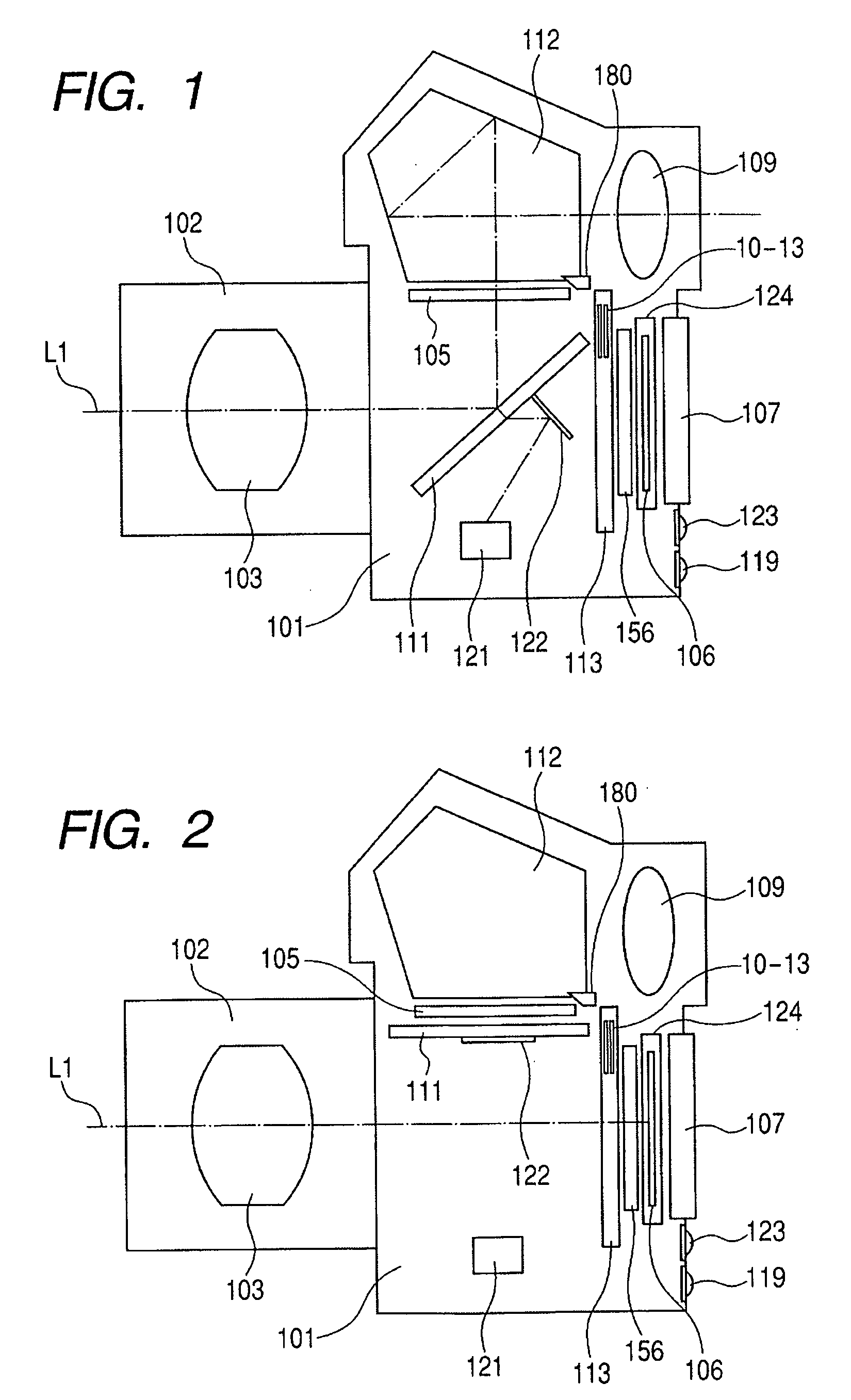
[0108] Details of the focal plane shutter 113 of the digital color camera system having the above-described structure according to the first embodiment will be described. FIGS. 4 and 5 are plan views showing the structure of the rear diaphragm. These drawings show the structure on the rear side of a shutter base plate that will be described later. FIG. 4 shows the state before shutter running starts and FIG. 5 shows the state after shutter running is completed.

[0109] In FIGS. 4 and 5, reference numeral 10 designates a rear diaphragm slit forming blade, reference numeral 10a designates the rear diaphragm slit forming edge. Designated by reference numerals 11 to 13 are rear diaphragm cover blades, where what are designated by reference numerals 11, 12 and13 are referred to as the second rear blade, the third rear blade, and the fourth rear blade respectively. The rear diaphragm slit forming blad...

second embodiment

[0211] In the following, the second embodiment of the present invention will be described.

[0212] In the second embodiment, a focal plane shutter 113 having a structure different from that of the above-described first embodiment is used. FIGS. 20 to 22 show the structure of the focal plane shutter 113 in the second embodiment of the present invention.

[0213]FIG. 20 is a schematic plan view showing the structure on the photographing lens unit 102 side of the shutter base plate 1 of the focal plane shutter 113 according to the second embodiment of the present invention at the start of shutter running in the shutter run-up zone. FIGS. 21 and 22 are plan views showing, in particular, the structure of the rear diaphragm. These drawings show the structure on the rear side of the shutter base plate 1. FIG. 21 shows the state before shutter running starts, and FIG. 22 shows the state after shutter running is completed. In FIGS. 20 to 22, the elements same as those in the first embodiment sh...

third embodiment

[0219] In the following, the third embodiment of the present invention will be described.

[0220] In the third embodiment, a focal plane shutter 113 having a structure different from that of the above-described first and second embodiments is used. FIGS. 23 to 25 show the structure of the focal plane shutter 113 in the third of the present invention.

[0221]FIG. 23 is a schematic plan view showing the structure on the photographing lens unit 102 side of the shutter base plate 1 of the focal plane shutter 113 according to the third embodiment of the present invention at the start of shutter running in the shutter run-up zone. FIGS. 24 and 25 are plan views showing, in particular, the structure of the rear diaphragm. These drawings show the structure on the rear side of the shutter base plate 1. FIG. 24 shows the state before shutter running starts, and FIG. 25 shows the state after shutter running is completed. In FIGS. 23 to 25, the elements same as those in the first embodiment shown...


PUM


Abstract

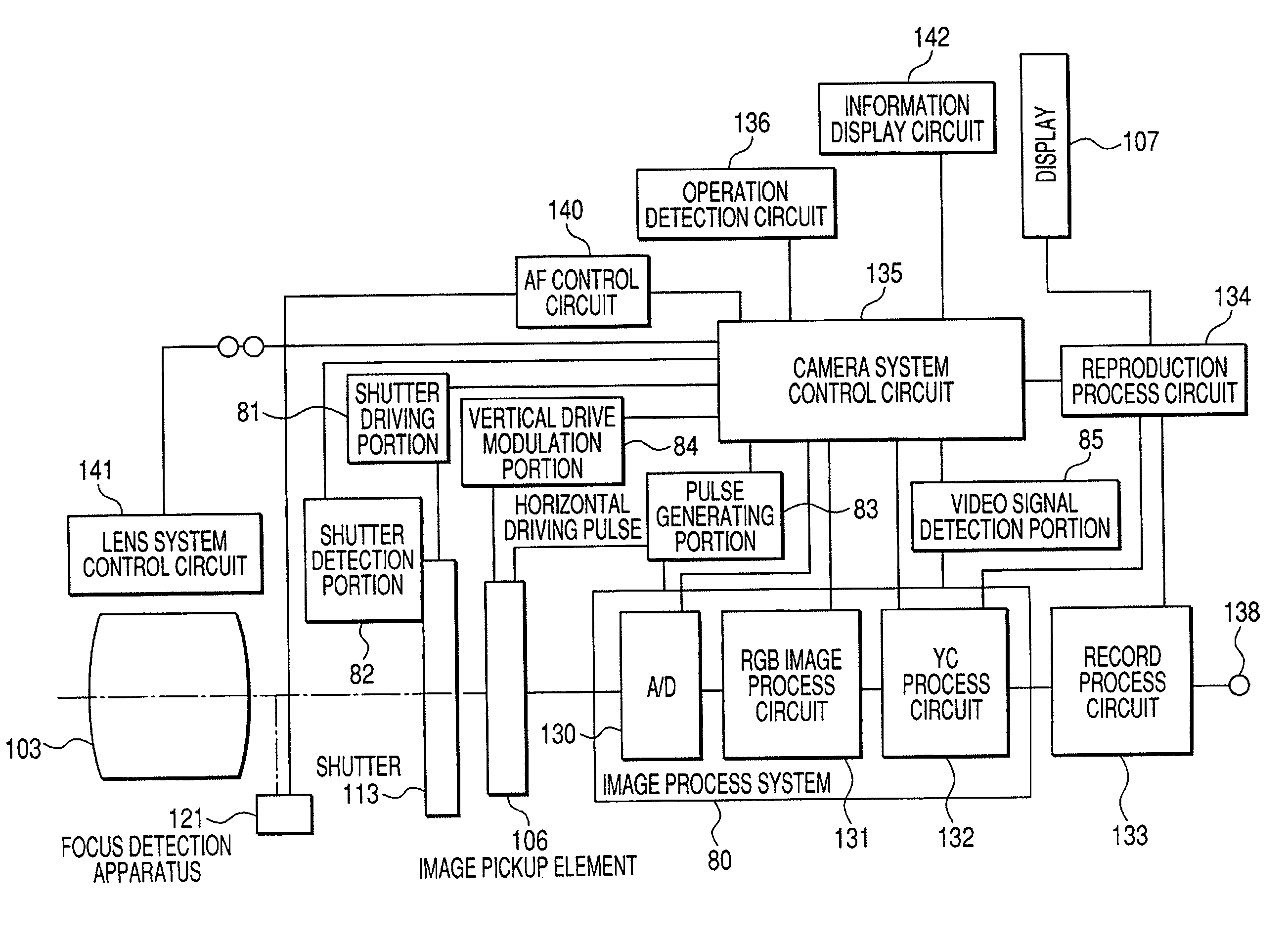
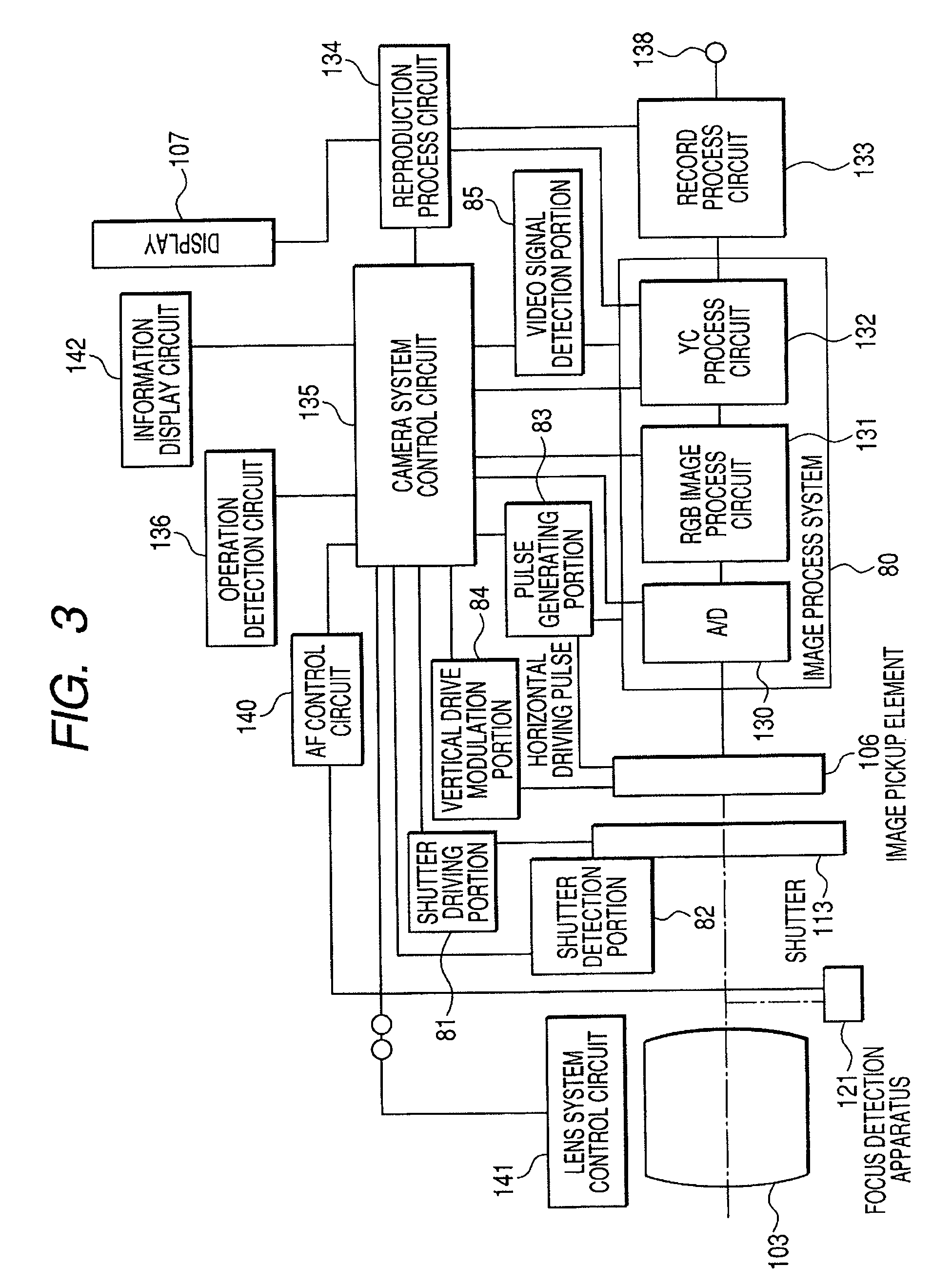
There is provided an image pickup apparatus having a simple structure that enables reduction of shutter release time lag and shutter control with highly accurate shutter time. The apparatus comprises an image pickup element that converts an optical object image incident thereon into an electric image signal to output it, a shutter apparatus having a screen for shielding an exposure aperture for the image pickup element, a reset circuit for reset scanning the image pickup element on a predetermined unit-batch-by-unit-batch basis sequentially in a running direction of the screen, a plurality of detection circuits disposed at different positions along the running direction of the screen for detecting passing of the screen after start of running of the screen for shielding the exposure aperture and before it runs over the exposure aperture, and a control circuit that estimates a running characteristic of the screen during running based on a detection result by the plurality of detection circuit and controls reset scanning by the reset circuit in conformity with the estimated running characteristic.

Description

BACKGROUND OF THE INVENTION [0001] 1. Field of the Invention [0002] The present invention relates to an image pickup method and a control method for the same, more particularly to an image pickup apparatus equipped with an image pickup element having an electronic shutter function, and a shutter apparatus for shielding such an image pickup element and a control method for the same. [0003] 2. Related Background Art [0004] Some conventional digital cameras achieve a viewfinder function that enables observation of an object to be photographed by sequentially displaying picked up images of the object on a monitor such as an LCD. In this type of digital cameras also, various shutter apparatuses can be used. [0005] In the following, some conventional shutter apparatuses will be described. [0006] Firstly, there is a shutter apparatus (a first shutter structure) used in silver-halide film cameras. This conventional shutter apparatus has two sets of diaphragm unit pivotally supported on a sh...

Claims


Application Information

Patent Timeline
IPC IPC(8): H04N5/235G03B9/36H04N5/225H04N5/335H04N5/353H04N5/372H04N5/374H04N5/376H04N101/00
CPCH04N5/2254H04N5/2353H04N23/73
Inventor TOYODA, YASUHIRO
Owner CANON KK
Learn More