Conveyor induct

a conveyor system and induction section technology, applied in the direction of conveyor control devices, conveyor parts, transportation and packaging, etc., can solve the problem of reducing the throughput of the conveying system

Active Publication Date: 2013-04-02
DEMATIC
View PDF25 Cites 38 Cited by
  • Summary
  • Abstract
  • Description
  • Claims
  • Application Information

AI Technical Summary

Benefits of technology

[0007]According to another embodiment, a method is provided for inducting articles in order to achieve a desired gap between leading and trailing edges of the articles. The method comprises controlling a first induct conveying surface such that the first induct conveying surface operates at a speed that will deliver an article on the first induct conveying surface to a downstream end of the first induct conveying surface at a first desired time. The method further includes controlling a second induct conveying surface, after the article arrives thereon, such that the second induct conveying surface operates at a speed that will deliver the article to a downstream end of the second induct conveying surface at a second desired time.

Problems solved by technology

However, gaps exceeding this minimum will generally decrease the throughput of the conveying system.

Method used


Image

  • Conveyor induct
  • Conveyor induct
  • Conveyor induct

Examples


Embodiment Construction

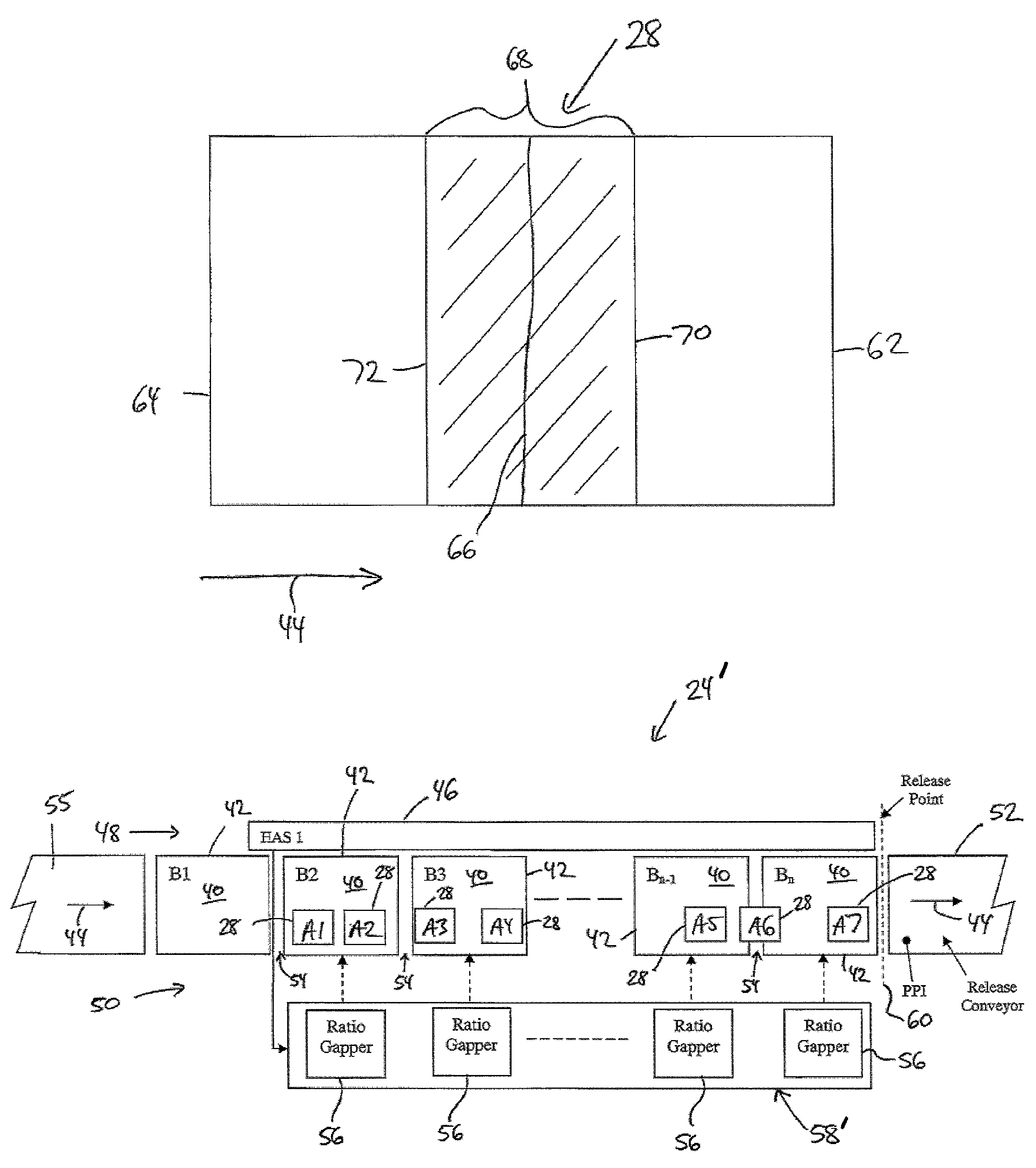
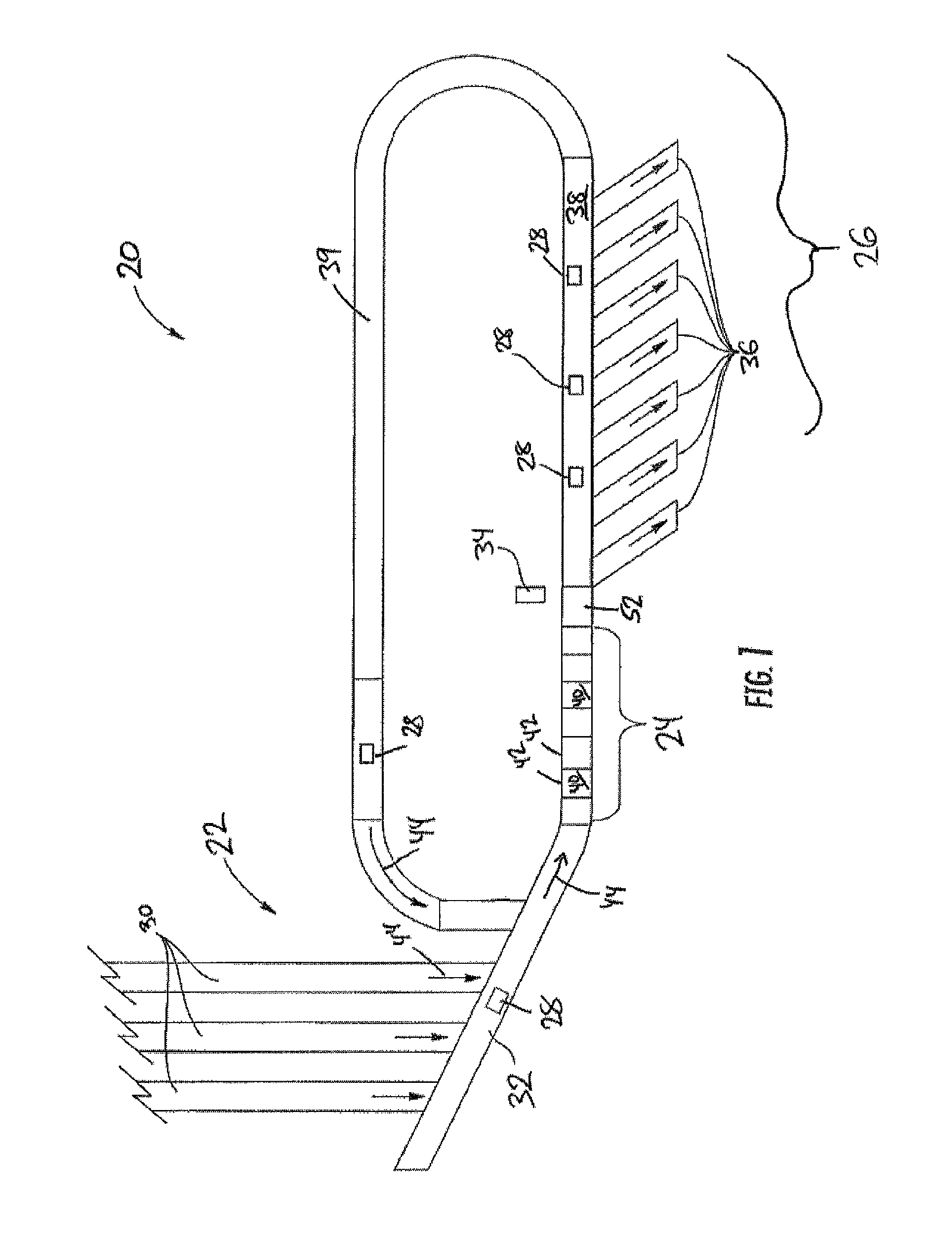
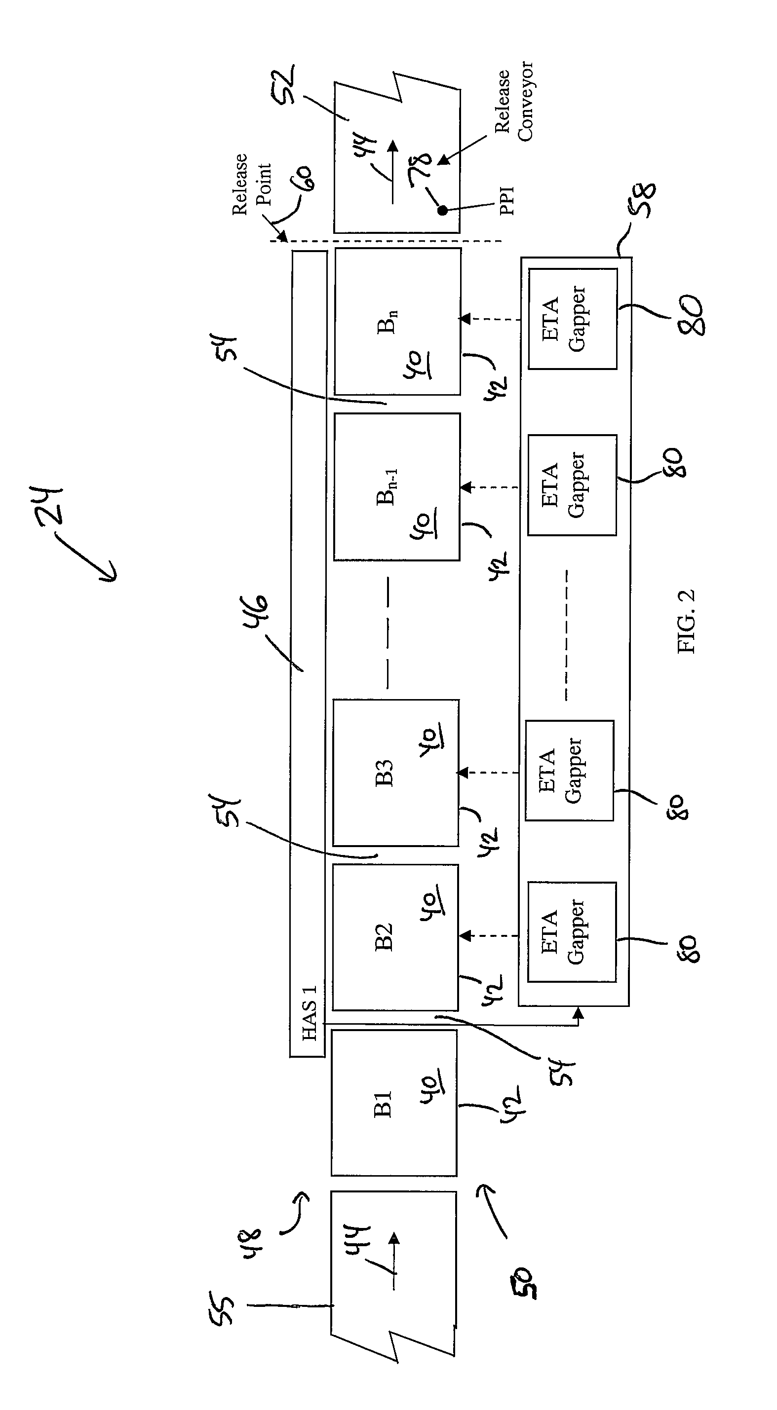
[0021]A conveying system 20 according to one embodiment is depicted in plan view in FIG. 1. The layout of conveying system 20 shown in FIG. 1 is an arbitrary layout that has been selected for purposes of further understanding the various embodiments. The layout of an actual conveying system will vary from that shown in FIG. 1 depending upon the warehouse or other facility in which the system 20 is incorporated. In general, conveying system 20 is adapted to convey articles 28, such as packages, retail products, etc. using a plurality of conveyors from a first location or set of locations to a destination or set of destinations. Conveying system 20 may be used in a product distribution center, a warehouse, a factory, a receiving and sortation facility, or other types of buildings or structures. The types of articles 28 that may be transported by conveying system 20 can vary widely, and it will be understood by those skilled in the art that the sizes and rectangular shapes of the artic...


PUM


Abstract

An induction subsystem for a conveying system includes a plurality of induction conveying units that are controlled by a plurality of controls in a manner that delivers articles to a release conveyor with gaps between the articles that approach a desired length. The conveying units may be controlled using algorithms that examine a planned release time for an article and a time at which the article would be released were it to complete the rest of its travel through the induction subsystem at one or more nominal speeds. The difference is used to determine an appropriate speed for at least one of the conveying units. The conveying unit may alternatively be controlled using algorithms that determine desired speed ratios for the conveying units, and which may seek to control the centerline to centerline spacing of articles as they reach the release point such that desired gaps are created.

Description

CROSS-REFERENCE TO RELATED APPLICATIONS[0001]This application claims priority to U.S. provisional application Ser. No. 61 / 237,953 filed Aug. 28, 2009, by Martin Doane and entitled CONVEYOR INDUCT, and U.S. provisional application Ser. No. 61 / 238,878 filed Sep. 1, 2009, by Martin Doane and entitled CONVEYOR INDUCT, the complete disclosures of both of which are hereby incorporated herein by reference in their entirety.BACKGROUND OF THE INVENTION[0002]The present invention relates to conveyor systems, and more particularly to the induction section of a conveyor system.[0003]Induction subsystems of conveying systems often serve the function of preparing articles on the conveying systems for being processed by a downstream sortation system. Such processing typically involves controlling the articles in such a way that the articles leaving the induction subsystem have gaps between them that are close to a desired length. The desired length may be variable depending upon the length and / or ...

Claims


Application Information

Patent Timeline
Patent Type & Authority Patents(United States)
IPC IPC(8): B65G47/31
CPCB65G43/08B65G47/506
Inventor DOANE, MARTIN R.
Owner DEMATIC
Why Eureka
Try Eureka