Exposure method, exposure apparatus, and method for producing device
a technology of exposure apparatus and substrate surface, which is applied in the direction of photomechanical apparatus, printers, instruments, etc., can solve the problems of insufficient margin and difficulty in matching the substrate surface with respect to the image plane of the projection optical system, and achieve the desired performance and satisfactory pattern transfer accuracy
- Summary
- Abstract
- Description
- Claims
- Application Information
AI Technical Summary
Benefits of technology
Problems solved by technology
Method used
Image
Examples
first embodiment
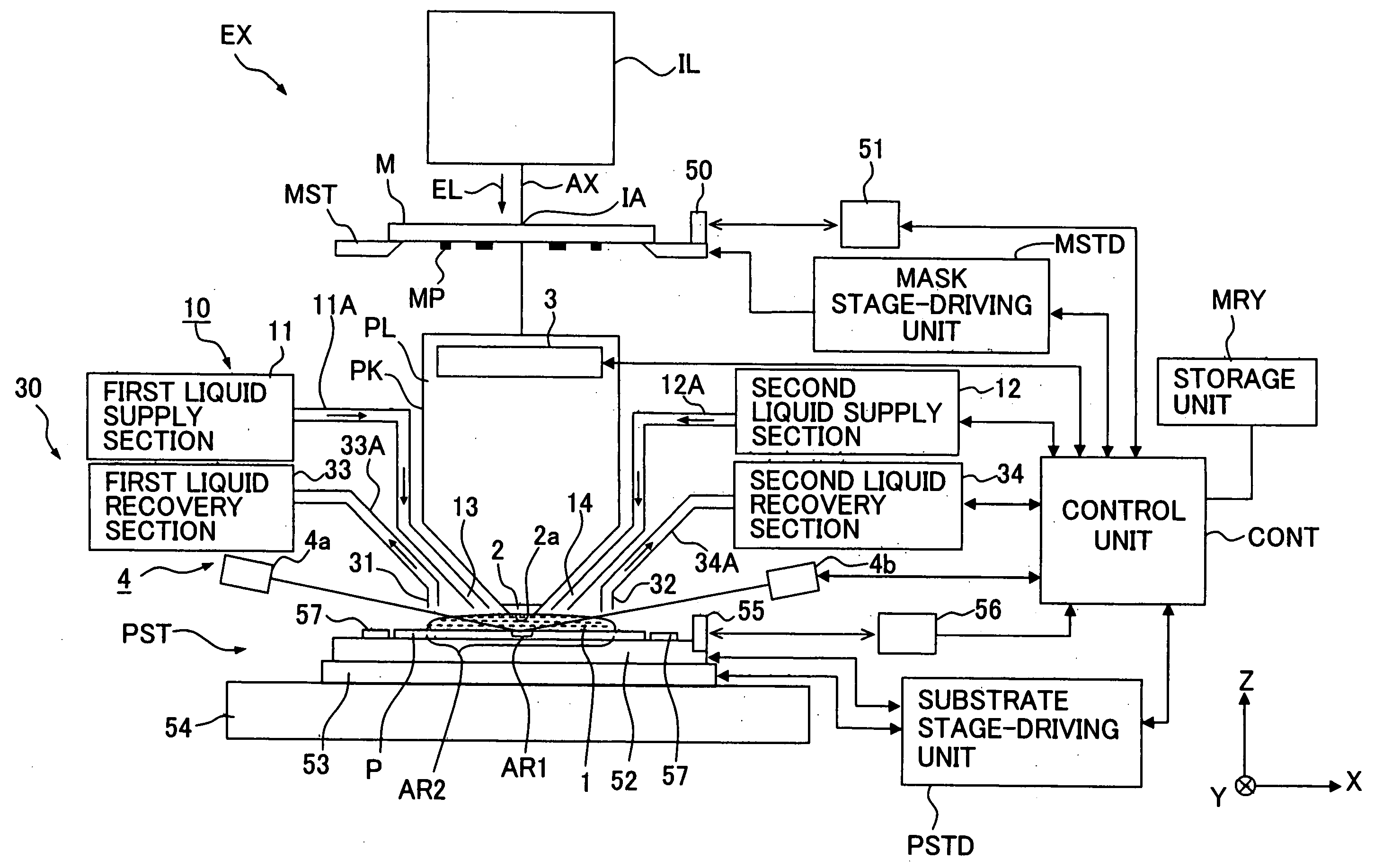
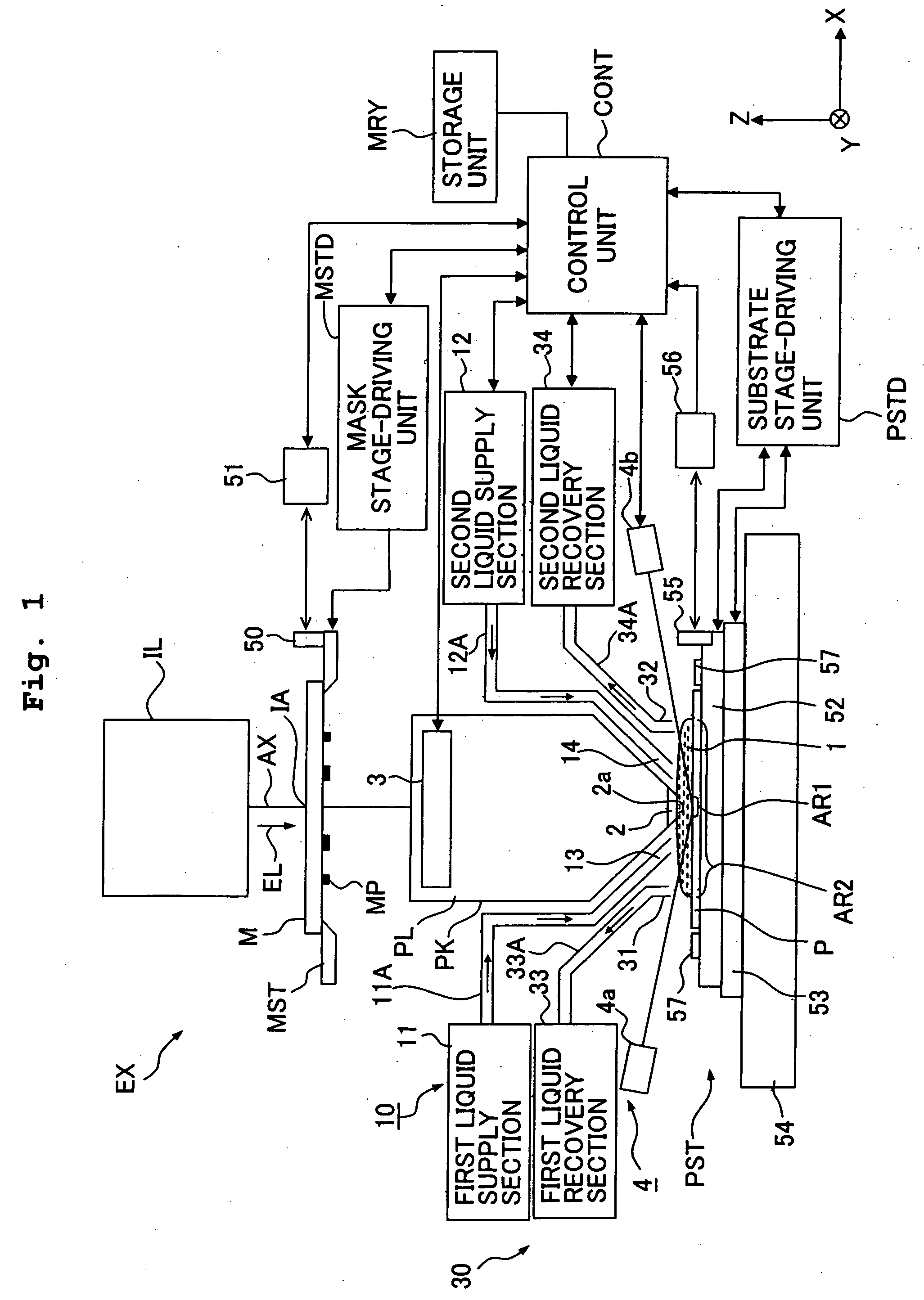
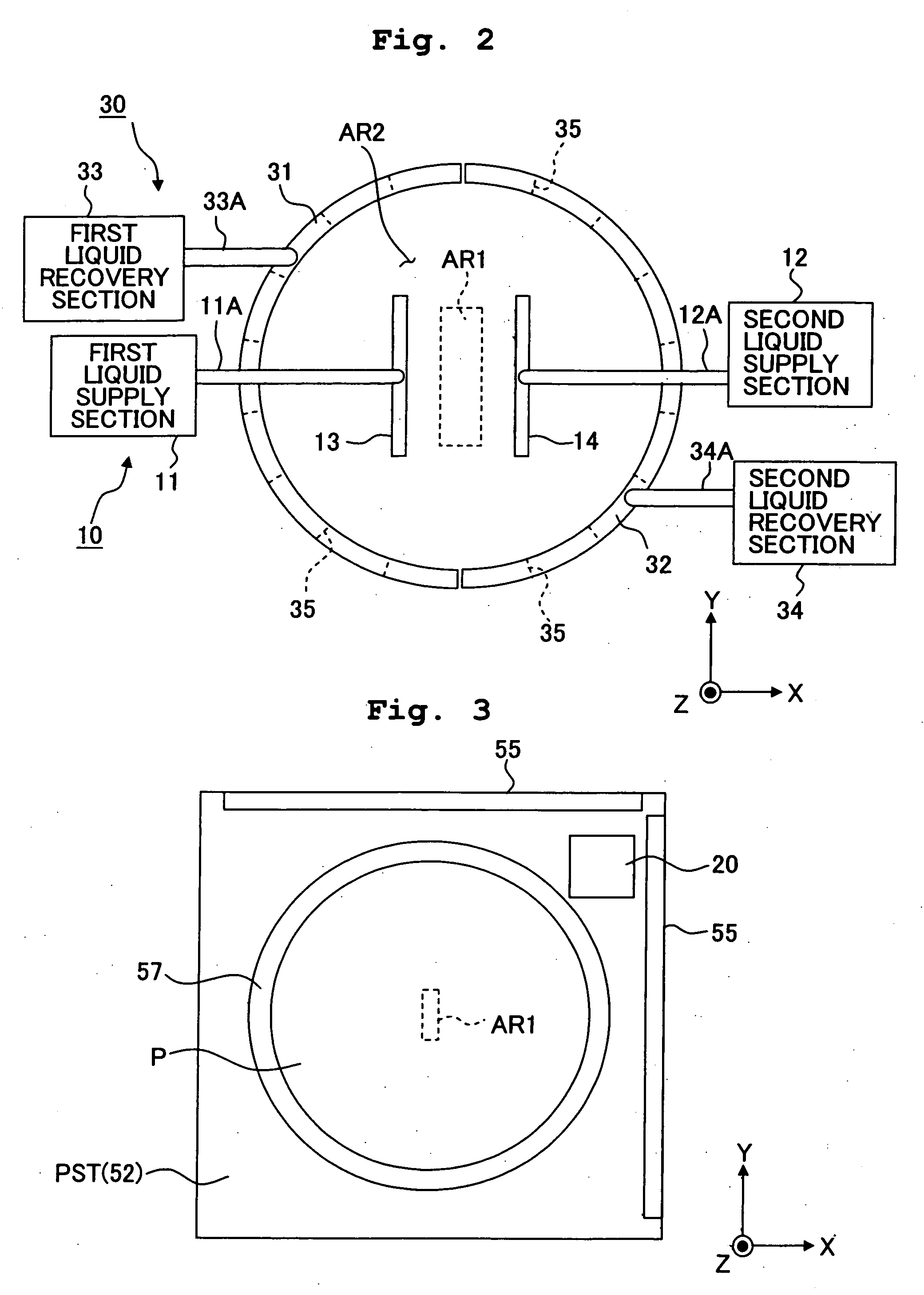
[0075]FIG. 1 shows a schematic arrangement illustrating a first embodiment of the exposure apparatus of the present invention. With reference to FIG. 1, an exposure apparatus EX principally includes a mask stage MST which supports a mask M, a substrate stage PST which supports a substrate P, an illumination optical system IL which illuminates, with an exposure light beam EL, the mask M supported by the mask stage MST, a projection optical system PL which performs projection exposure for the substrate P supported by the substrate stage PST with an image of a pattern of the mask M illuminated with the exposure light beam EL, a control unit CONT which collectively controls the overall operation of the exposure apparatus EX, and a storage unit MRY which is connected to the control unit CONT and which stores various pieces of information about the exposure operation including information about the distribution of the pattern MP of the mask M.
[0076] The exposure apparatus EX of this embo...
second embodiment
[0128] Next, an explanation will be made about a second embodiment of the exposure apparatus of the present invention with reference to FIG. 10. In this embodiment, the projection state is adjusted by making the adjustment so that any temperature distribution is not generated in the liquid 1 of the liquid immersion area AR2 depending on the pattern distribution of the mask M (distribution of the exposure light beam EL which comes into the projection area AR1), i.e., so that the temperature distribution of the liquid 1 is uniformized. In particular, the adjustment is made so that the temperature distribution is uniform in the Y axis direction as the direction perpendicular to the scanning direction (X axis direction). This embodiment is constructed in the same manner as the first embodiment except for the liquid supply mechanism. In the following explanation, the constitutive portions, which are the same as or equivalent to those of the first embodiment described above, are designate...
third embodiment
[0139] Next, an explanation will be made with reference to FIG. 11 about a third embodiment of the exposure apparatus EX of the present invention. In this embodiment, the liquid supply mechanism and the liquid recovery mechanism are changed as follows. As shown in FIG. 11, the exposure apparatus EX includes a liquid supply mechanism 10 which has two supply tubes 71, 72 (supply ports 71A, 72A) provided and aligned in the Z axis direction as the direction perpendicular to the X axis direction, and a liquid recovery mechanism 30 which has two recovery tubes 73, 74 (recovery ports 74A, 74A) provided and aligned in the Z axis direction so that the recovery tubes 73, 74 are opposed to the supply tubes 71, 72. The liquid supply mechanism 10 is capable of supplying the liquid from the respective supply ports 71A, 72A at mutually different temperatures. Accordingly, two liquid layers LQ1, LQ2, which have temperatures different from each other, can be formed in the liquid immersion area AR2. ...
PUM
| Property | Measurement | Unit |
|---|---|---|
| refractive index | aaaaa | aaaaa |
| wavelength | aaaaa | aaaaa |
| wavelength | aaaaa | aaaaa |
Abstract
Description
Claims
Application Information
 - R&D
- Intellectual Property
- Life Sciences
- Materials
- Tech Scout
- Unparalleled Data Quality
- Higher Quality Content
- 60% Fewer Hallucinations
Browse by: Latest US Patents, China's latest patents, Technical Efficacy Thesaurus, Application Domain, Technology Topic, Popular Technical Reports.
© 2025 PatSnap. All rights reserved.Legal|Privacy policy|Modern Slavery Act Transparency Statement|Sitemap|About US| Contact US: help@patsnap.com


