
Apparatus and method for matrix data processing

a matrix data and matrix processing technology, applied in the field of digital signal processing, can solve the problems of wasting processor bandwidth and other processing inefficiencies, consuming precious cycle time and energy waiting, and increasing signal processing times, so as to achieve rapid processing of polynomial operations and improve the performance of digital signal processing operations.

Inactive Publication Date: 2006-05-11
GEMTECH SYST
View PDF1 Cites 72 Cited by
  • Summary
  • Abstract
  • Description
  • Claims
  • Application Information

AI Technical Summary

Benefits of technology

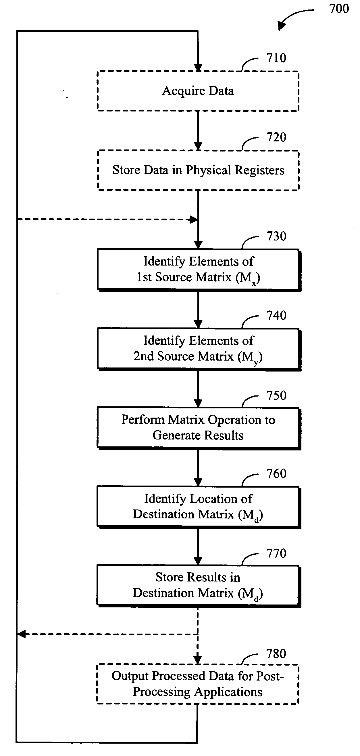
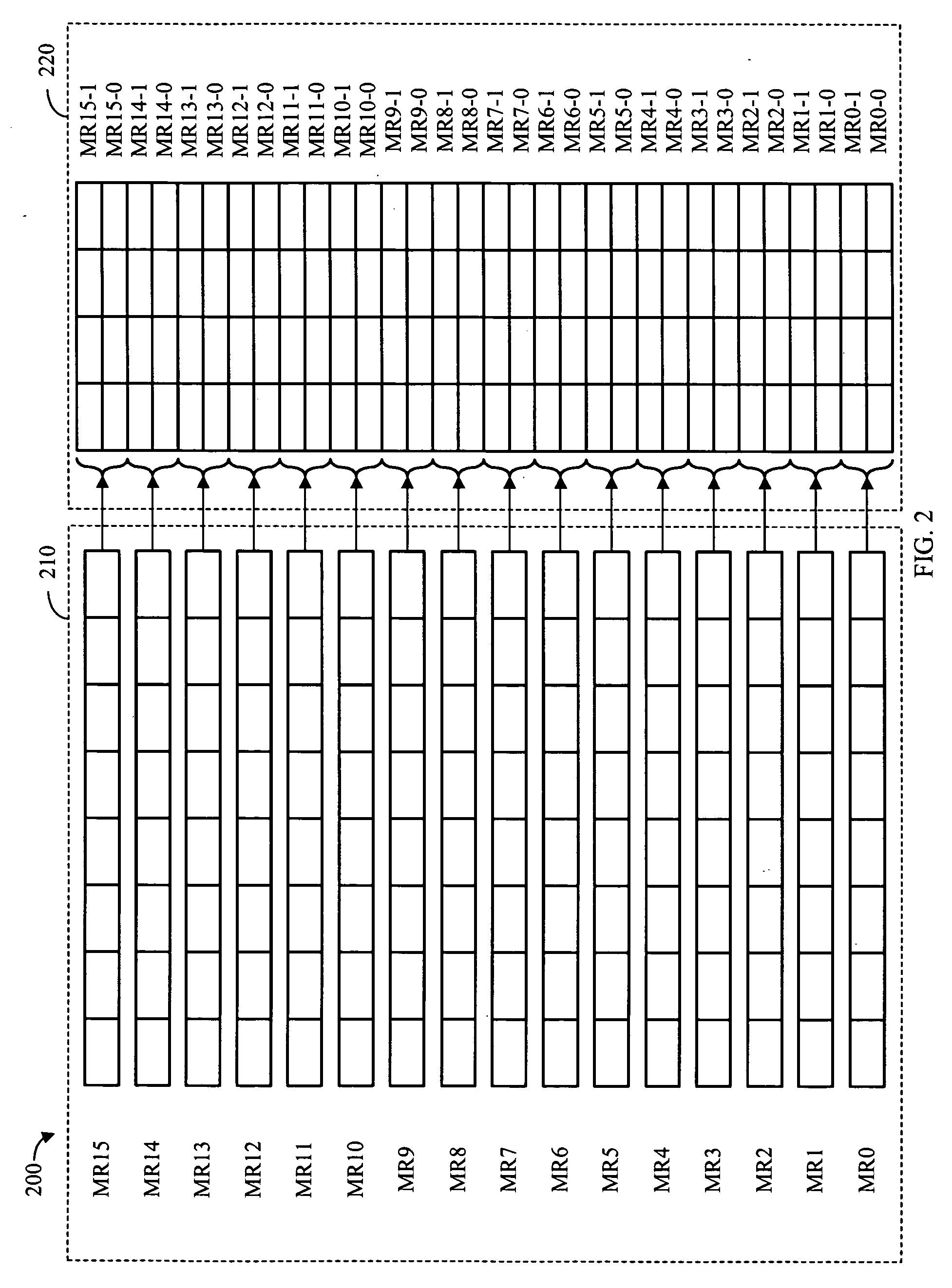
[0012] A matrix data processor is implemented wherein data elements are stored in physical registers and mapped to logical registers. The matrix data processor includes an arithmetic logic unit and a register set. The register set includes multiple configuration registers where each configuration register contains one or more matrix parameters that are configured to describe and identify a first source matrix, a second source matrix, and a destination matrix. After being stored in the logical registers, the data elements are then treated as matrix elements. By using the matrix parameters to define the size and location of the various matrix source and destination elements, as well as the operation(s) to be performed on the matrices, the performance of digital signal processing operations can be significantly enhanced. Additionally, the operand matrices can be used to represent polynomial coefficients, thereby enabling rapid processing of polynomial operations and the implementation of operations in alternate number systems including Galois Fields.

Problems solved by technology

This disparity in the size of the data representations results in wasted processor bandwidth and other processing inefficiencies.
This inefficient use of available storage results in resource underutilization, which generally leads to increased signal processing times. In general, this inefficient processing can lead to “data-starvation” for the microprocessor, and the microprocessor consumes precious cycle time and energy waiting for data to arrive instead of processing data.
This technique, while successfully utilizing the available storage space, requires relatively complex indexing algorithms to effect data retrieval and manipulation.
However, even after implementing these various techniques, the microprocessors used in many digital signal-processing systems remain “data-starved” and underutilized.
This situation is undesirable because the lack of timely data presentation can, in certain circumstances, add additional processing cycles and, correspondingly, slow down the overall operation of the devices utilizing the processed signal.
Additionally, in the case of certain applications such as processing error correction codes and enabling and implementing encryption protocols for on-line data transfer, the manipulation of the data can be based on complex polynomial operations, leading to significant processing overhead.
This type of data processing can consume precious processor cycles, thereby slowing down the overall response time of the system and delaying further processing until the data can be processes and formatted for use in the desired application.
Since most data processors are not optimized for polynomial operations, the loss of processing power can be significant.

Method used


Image

  • Apparatus and method for matrix data processing
  • Apparatus and method for matrix data processing
  • Apparatus and method for matrix data processing

Examples


Embodiment Construction

[0023] The matrix data processor of the present invention stores data elements in physical registers and maps the data elements to logical registers. The matrix data processor then performs data processing operations by treating the data elements in the logical registers as elements of matrices. By using a series of variables to define the size and location of the matrix elements, as well as the operation(s) to be performed on the matrix elements, the performance of digital signal processing operations can be significantly enhanced.

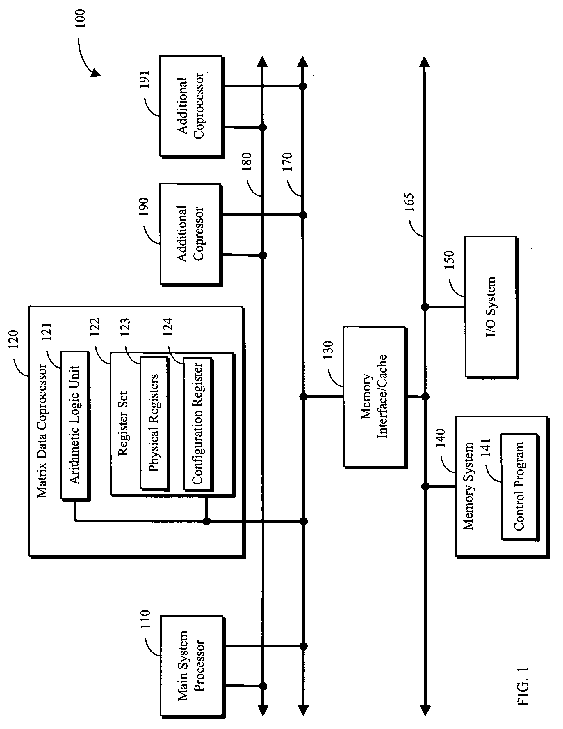
[0024] Referring now to FIG. 1, a matrix data processing system 100 in accordance with a preferred embodiment of the present invention comprises a main system processor 110, a matrix data processor 120, one or more optional coprocessors 190 and 191, a memory interface / cache 130, a memory system 140, and an I / O system 150. Main system processor 110, coprocessors 120, 190 and 191, and memory interface / cache 130 are coupled via a bus 170. Bus 170 provides a...


PUM

PropertyMeasurementUnit
speedaaaaaaaaaa
signal processing capabilitiesaaaaaaaaaa
sizeaaaaaaaaaa

Abstract

A matrix data processor is implemented wherein data elements are stored in physical registers and mapped to logical registers. After being stored in the logical registers, the data elements are then treated as matrix elements. By using a series of variable matrix parameters to define the size and location of the various matrix source and destination elements, as well as the operation(s) to be performed on the matrices, the performance of digital signal processing operations can be significantly enhanced.

Description

RELATED APPLICATION [0001] This application is a continuation-in-part of U.S. patent application Ser. No. 10 / 315,700 filed on Dec. 9, 2002, now issued as U.S. Pat. No. 6,9447,47, which patent is incorporated herein by reference.BACKGROUND OF THE INVENTION [0002] 1. Technical Field [0003] The present invention relates generally to digital signal processing and more particularly to relatively high-speed signal processing for various applications, such as communications. [0004] 2. Background Art [0005] Signal processing may be described as the mathematical manipulation of signals in a predetermined manner to enhance, modify or otherwise alter the signal, typically to prepare the signal for additional post-processing applications. The input signals are often “sampled” data elements taken from various forms of analog signals such as voice, video, and various communication sources. After sampling, these analog signals may be processed by a variety of electronic systems to accomplish the d...

Claims


Application Information

Patent Timeline
Patent Type & Authority Applications(United States)
IPC IPC(8): G06F9/44G06F9/30G06F9/302G06F9/345G06F9/38G06F15/00G06F17/16G11B
CPCG06F9/30014G06F9/30036G06F9/30098G06F9/30145G06F9/345G06F9/3879G06F9/3887G06F9/3001G06F9/30109G06F9/30101
Inventor NAIR, GOPALANSEKHAR, ARCHANADAVID, PRASANTHJOSE, ANTONY
Owner GEMTECH SYST
Learn More