Flexible sheet for resistive touch screen

a flexible sheet and touch screen technology, applied in the field of resistive touch screen, can solve the problems of reducing the clarity of the touch screen, reducing the material availability of prior-art spacer dots, and relatively complex process, and achieves the effects of simple manufacturing, greater accuracy, and robustness

a flexible sheet and touch screen technology, applied in the field of resistive touch screen, can solve the problems of reducing the clarity of the touch screen, reducing the material availability of prior-art spacer dots, and relatively complex process, and achieves the effects of simple manufacturing, greater accuracy, and robustness

US20060102463A1Active Publication Date: 2006-05-18EASTMAN KODAK CO

Image

  • Flexible sheet for resistive touch screen
  • Flexible sheet for resistive touch screen
  • Flexible sheet for resistive touch screen

Examples


Embodiment Construction

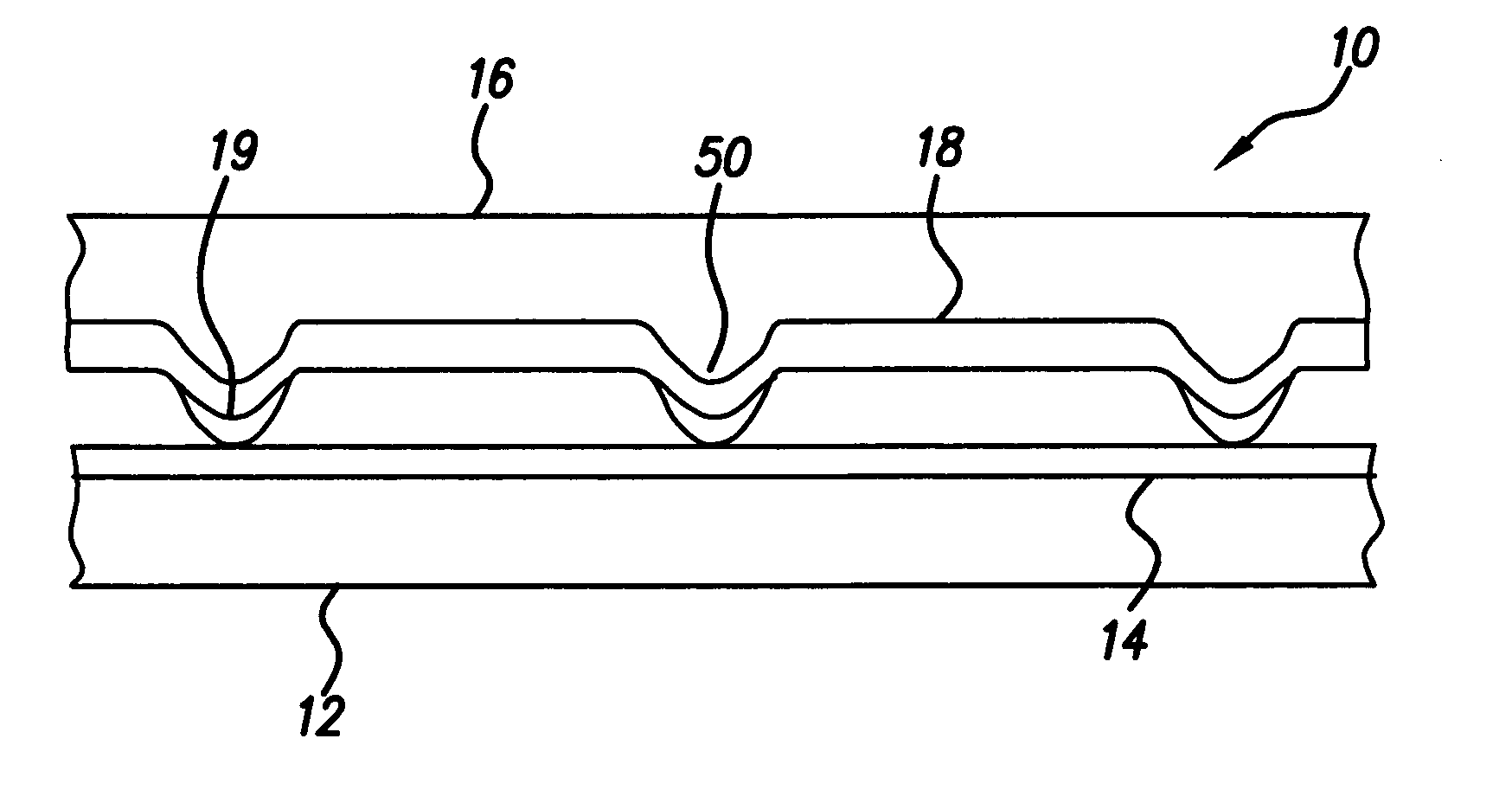
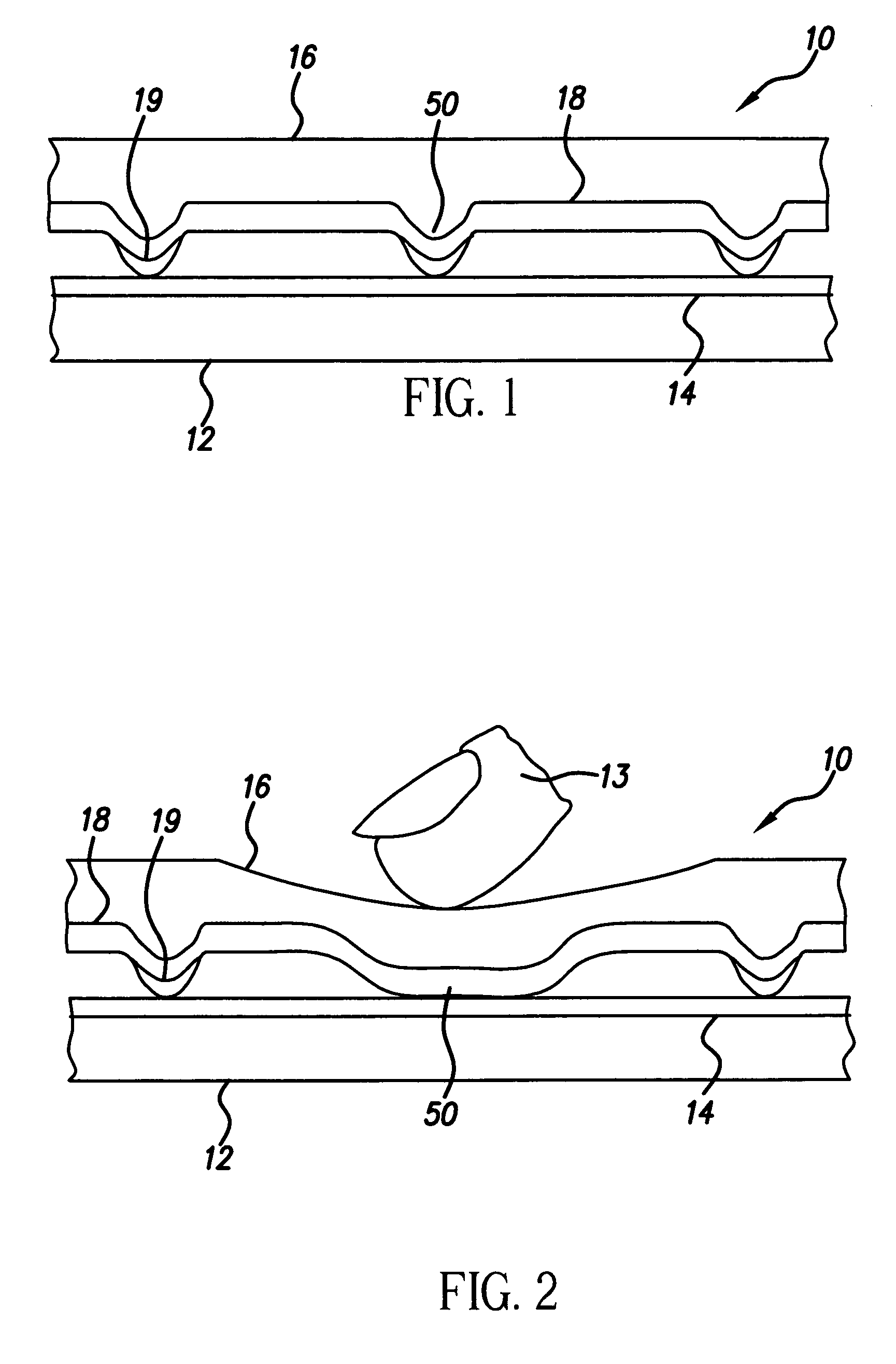
[0021] Referring to FIG. 1, the problems of the prior-art resistive touch screens are overcome through the use of a flexible cover sheet 16 having a second conductive layer 18 and integral compressible spacer dots 50 formed in the flexible cover sheet 16. The second conductive layer 18 on the flexible cover sheet 16 covers the peaks of the integral compressible spacer dots 50, and an insulative layer 19 is formed locally over the peaks of the integrated compressible spacer dots, as illustrated in further detail in FIG. 7 discussed below. The word “integral” means that the compressible spacer dots 50 are formed in and comprise the same material as the flexible cover sheet 16 for example by molding or embossing.

[0022] The insulative layer 19 formed over the integral compressible spacer dots 50 prevents the second conductive layer 18 deposited on the flexible cover sheet 16 from touching the first conductive layer 14 on substrate 12 of the touch screen 10. Because the peaks of the sec...


PUM


Abstract

A resistive touch screen, comprising: a) a substrate; b) a first conductive layer located on the substrate; c) a flexible cover sheet having integral compressible spacer dots; d) a second conductive layer located on the flexible cover sheet between and over the integral spacer dots; and e) an insulative layer located on the second conductive layer locally over the integral spacer dots.

Description

FIELD OF THE INVENTION [0001] This invention relates to resistive touch screens and more particularly, to a flexible cover sheet and spacer dots separating the cover sheet from a substrate in a resistive touch screen. BACKGROUND OF THE INVENTION [0002] Resistive touch screens are widely used with conventional CRTs and flat-panel display devices in computers and in particular with portable computers. [0003]FIG. 3 shows a portion of a prior-art resistive touch screen 10 of the type shown in Published US Patent Application No. 2002 / 0094660A1, filed by Getz et al., Sep. 17, 2001, and published Jul. 18, 2002, which includes a rigid transparent substrate 12, having a first conductive layer 14. A flexible transparent cover sheet 16 includes a second conductive layer 18 that is physically separated from the first conductive layer 14 by spacer dots 20 formed on the second conductive layer 18 by screen printing. [0004] Referring to FIG. 4, when the flexible transparent cover sheet 16 is defor...

Claims


Application Information

Patent Timeline
18 May 2006
Publication
US20060102463A1
IPC
H01H1/10
CPC
G06F3/045; H01H13/702; H01H2209/002; H01H2211/02; H01H2211/026; H01H2221/002; H01H2229/044; H01H2239/064
Inventors
COK, RONALD S.