Coaxial rotorcraft control system

a control system and coaxial technology, applied in the direction of rotorcraft, vehicles, aircraft, etc., can solve the problems of unbalance torque, increased pitch, and limited development of this type of aircraft, and achieve the effect of simplifying design and reducing cos

Inactive Publication Date: 2006-05-18
AIRSCOOTER CORP
View PDF67 Cites 80 Cited by
  • Summary
  • Abstract
  • Description
  • Claims
  • Application Information

AI Technical Summary

Benefits of technology

[0008] It has been recognized that instead of a differential collective where the blade pitch of one rotor is increased as that of the other is decreased, and vice versa, by the same amount, that collective inputs of different amounts can be made to the respective rotors of the rotor set. In one example, a single collective blade pitch control of one rotor only can provide a yaw attitude control input for the coaxial rotorcraft a coaxial rotorcraft. Commensurate potential advantages of performance achievable for potentially lower cost also argue for simplification in design. In one example a control system for a rotorcraft having a coaxial rotor set including a first rotor carried by a first drive shaft, and a second counter-rotating rotor carried by a second drive shaft, has a collective pitch control which provides a yaw attitude control input via a collective control input to one rotor, without providing a collective control input to the other rotor. In a more detailed aspect, the rotorcraft can have another collective control system which is essentially independent of the yaw control collective, providing a separate control input for rotor thrust and a separate control input for yaw. This can still be simpler than providing a differential collective where one increases while the other decreases by the same amount. Common to these is that a yaw attitude control input is provided by enabling a different blade pitch magnitude for the first rotor as compared to the second rotor, thereby unbalancing the torque forces in the coaxial rotor set.

Problems solved by technology

However, because of difficulties involved in the control of cyclic and collective pitch of rotor blades in a coaxial configuration, development of this type of aircraft has heretofore been limited.
Pitch is increased in one rotor, and decreased in the other, to unbalance torque.
Common to these is that a yaw attitude control input is provided by enabling a different blade pitch magnitude for the first rotor as compared to the second rotor, thereby unbalancing the torque forces in the coaxial rotor set.

Method used


Image

  • Coaxial rotorcraft control system
  • Coaxial rotorcraft control system
  • Coaxial rotorcraft control system

Examples


Embodiment Construction

)

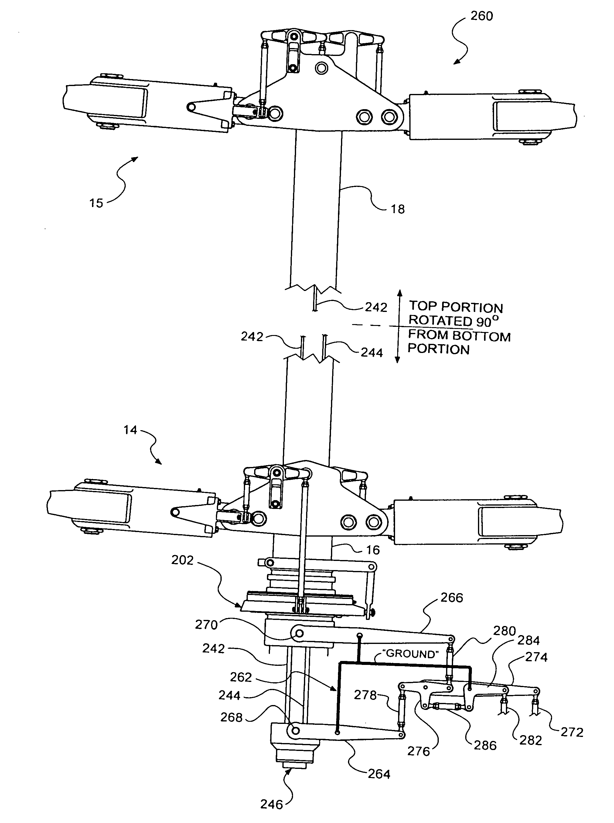
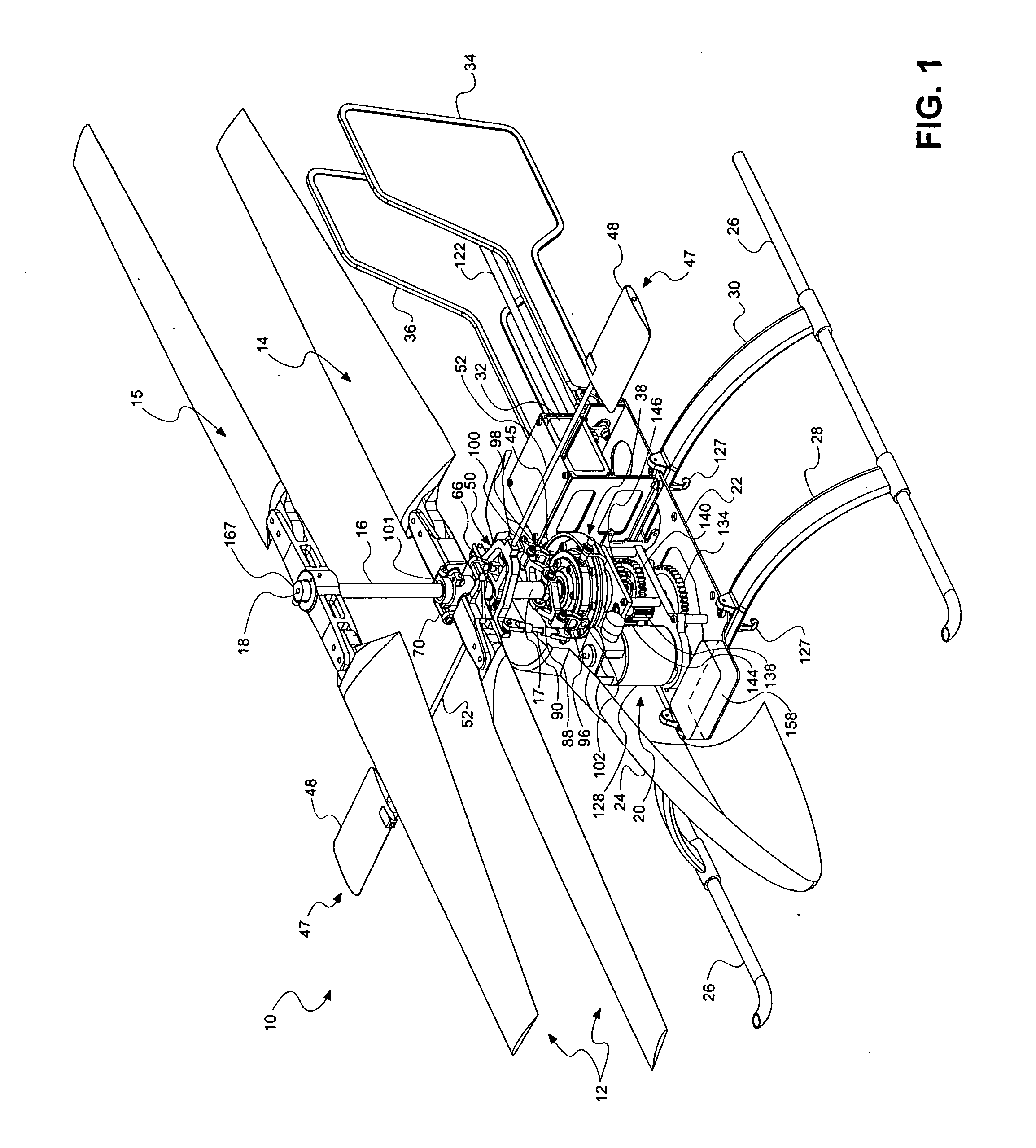
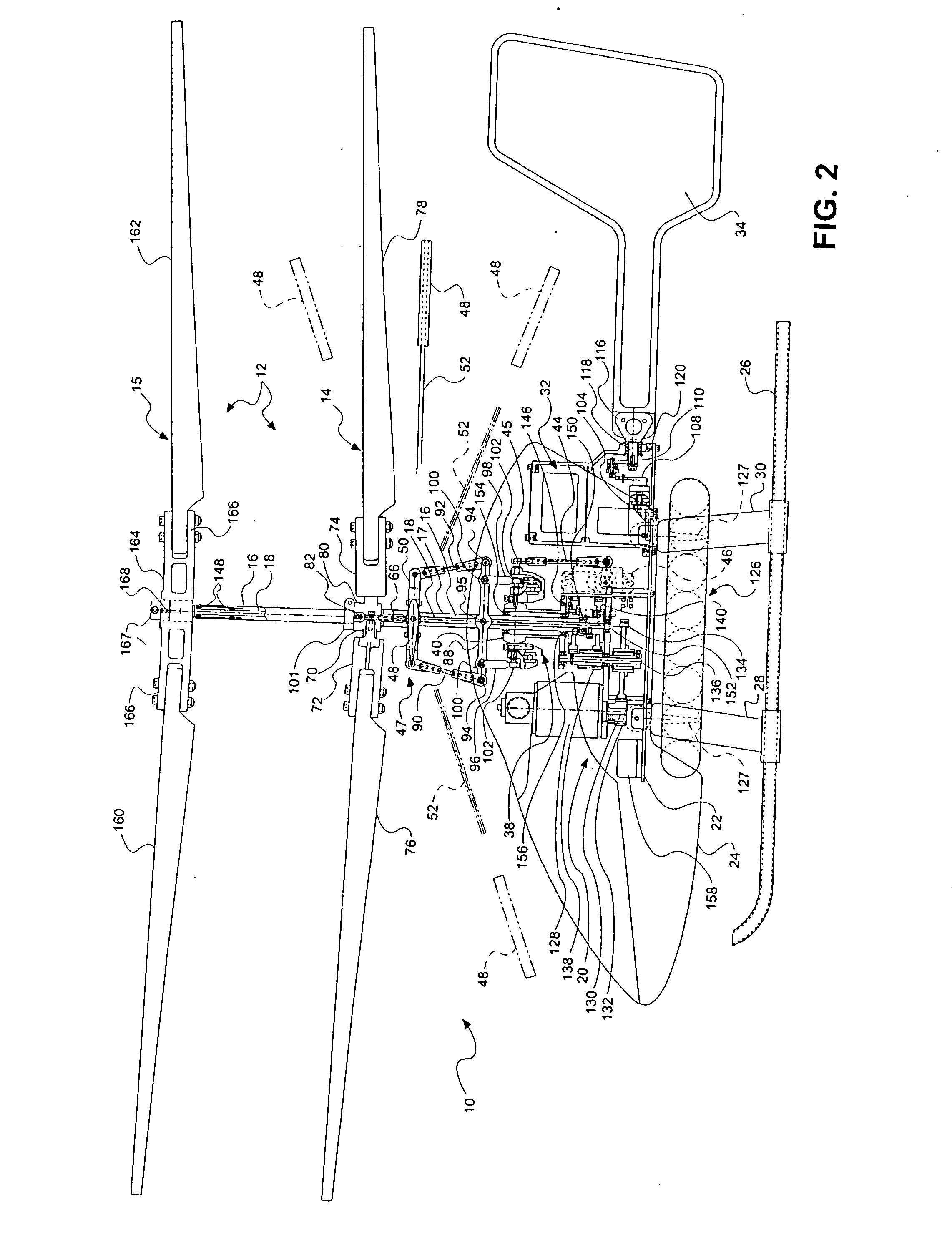
[0030] With reference to FIGS. 1, 2, 3 and 4 of the drawings, which are provided by way of illustration, and not by way of limitation, the invention can be embodied in a model helicopter rotorcraft 10 comprising a coaxial rotor set 12 including a lower rotor 14 and an upper rotor 15 which are carried and actuated by an outer drive shaft 16 and an inner drive shaft 18, respectively. An outer tube 17 overlays the outer driveshaft, and will be further described below. The driveshafts are powered by a power assembly 20 carried by an airframe 22 comprising all supporting structure of the aircraft to which the various components are attached or are ultimately carried by.

[0031] The illustrated embodiment is a model helicopter 10, but as will be appreciated, the invention can be incorporated in larger aircraft. The model aircraft includes a canopy 24 which is supported by the airframe 22 and provides an outer covering for the model helicopter, and which may be shaped and painted to resemb...


PUM


Abstract

A control system for a coaxial rotorcraft comprises a coaxial rotor set, further comprising an upper rotor actuated by a first drive shaft and a lower rotor actuated by a second drive shaft, the lower rotor having a direction of rotation counter to a direction of rotation of the upper rotor. A collective blade pitch control is configured to: collectively control pitch of only one of the upper rotor and the lower rotor and not another of the upper rotor and the lower rotor; and create an unbalanced torque force which acts on the rotorcraft and which enables a yaw attitude control input through said collective blade pitch control.

Description

[0001] This is a continuation-in-part of U.S. patent application Ser. No. 09 / 782,941, filed Feb. 14, 2001, the disclosure of which is hereby incorporated herein by reference for the teachings consistent herewith: but to the extent inconsistent herewith, this disclosure shall control.BACKGROUND [0002] 1. Field of the Invention [0003] The invention relates to rotorcraft flight control systems. More particularly, the invention relates to a flight control system arrangement for a coaxial helicopter vehicle. [0004] 2. Description of Related Art [0005] Coaxial helicopters have been known for many years. However, because of difficulties involved in the control of cyclic and collective pitch of rotor blades in a coaxial configuration, development of this type of aircraft has heretofore been limited. Conventional coaxial designs provide roll, pitch and yaw control by providing control input linkages for cyclic and collective pitch to both an upper rotor and a lower rotor of a coaxial rotor s...

Claims


Application Information

Patent Timeline
Patent Type & Authority Applications(United States)
IPC IPC(8): B64C27/52B64C27/10
CPCB64C27/10
Inventor ROCK, EUGENE F.
Owner AIRSCOOTER CORP
Why Eureka
Try Eureka