
Method and apparatus for timing calibration in a PET scanner

Inactive Publication Date: 2006-05-18
GENERAL ELECTRIC CO
View PDF14 Cites 70 Cited by
  • Summary
  • Abstract
  • Description
  • Claims
  • Application Information

AI Technical Summary

Problems solved by technology

If the two opposite blocks have different timing characteristics, radiation events detected along the LOR connecting the two blocks may exhibit a timing drift, therefore causing difficulty in reconstructing PET images or causing errors in the reconstructed images.
Timing drifts are typically caused by changes in time delay inside the PMTs, change in thresholds in the time-stamping circuits, master clock skew, or transmission delays in the cables.
The use of an external radiation source requires interruptions to normal operation of the PET scanner.
As a result, the traditional timing calibration cannot be performed concurrently with data acquisition from patients.

Method used


Image

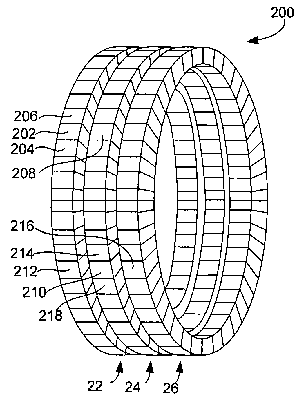
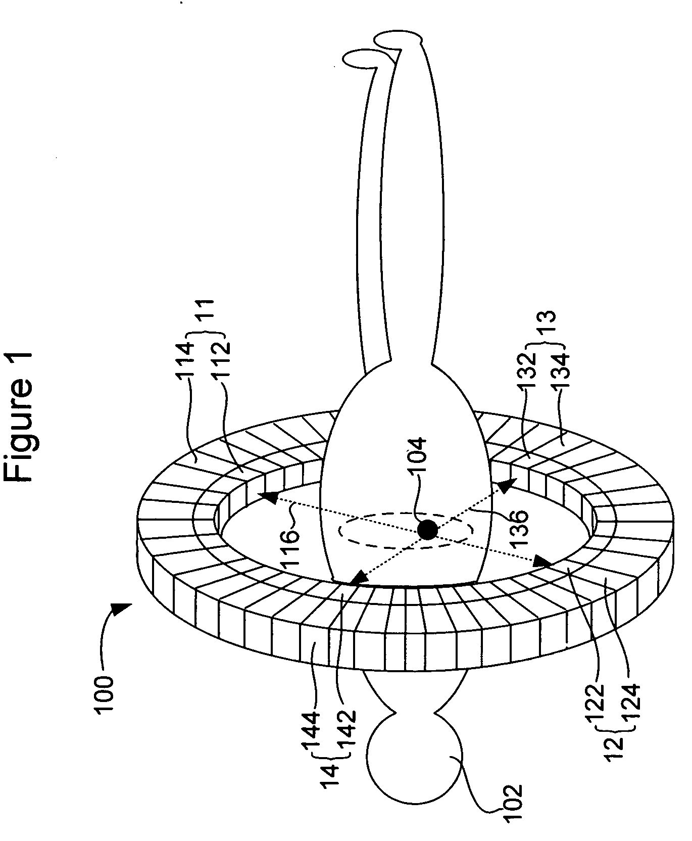
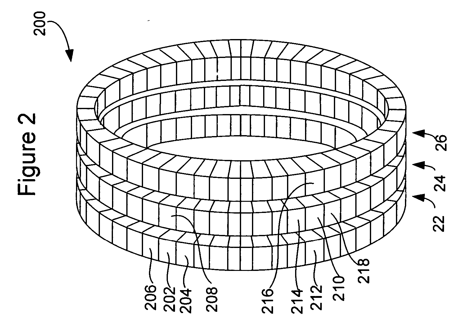
  • Method and apparatus for timing calibration in a PET scanner
  • Method and apparatus for timing calibration in a PET scanner
  • Method and apparatus for timing calibration in a PET scanner

Examples


Embodiment Construction

[0020] Reference will now be made in detail to exemplary embodiments of the invention, examples of which are illustrated in the accompanying drawings.

[0021] One technical effect of the invention is to provide a method and apparatus for timing calibration in a PET scanner, as set forth in the Brief Summary of the Invention, above and as more fully described here in the Detailed

DESCRIPTION OF THE INVENTION

[0022] Embodiments of the present invention may achieve timing calibration in a PET scanner without using any external radiation sources. Instead, timing drifts may be measured based on intrinsic radiation events in the scintillator blocks. For example, many high-speed scintillators for TOF PET contain lutetium (Lu), a naturally radioactive substance. FIG. 3 is a diagram illustrating the energy states involved in a lutetium beta decay. As shown, multiple gamma rays may be emitted when lutetium (176Lu) decays to hafnium (176Hf). The total energy of these gamma rays is 597 keV. Acco...


PUM


Abstract

The invention is directed to a method and apparatus for timing calibration in a PET scanner. According to one embodiment, the invention relates to a method for timing calibration in a PET scanner having a plurality of scintillator blocks. The method comprises: detecting, in a first scintillator block, a first radiation event, wherein the first scintillator block time-stamps the first radiation event; detecting, in a second scintillator block that is adjacent to the first scintillator block, a second radiation event that corresponds to the first radiation event, wherein the second scintillator block time-stamps the second radiation event; and determining a timing characteristic of the first scintillator block with respect to the second scintillator block based on a comparison between the time-stamps of the first radiation event and the second radiation event.

Description

BACKGROUND OF THE INVENTION [0001] The present invention relates generally to the field of medical imaging and more particularly to a method and apparatus for timing calibration in a PET scanner. [0002] Positron emission tomography (PET) is a technique commonly used in clinical medicine and biomedical research to create images of a living body in its active state. PET scanners can produce images that illustrate various biological process and functions. In a PET scan, the patient is initially injected with a radioactive substance known as a PET isotope. The injected PET isotope can act as a tracer when it becomes involved in certain physiological processes in the patient's body. Typical positron-emitting PET isotopes include 11C, 13N, 15O and 18F. When positrons are emitted within the body, they combine with electrons in the neighboring tissues and become annihilated. The annihilation event mostly result in a pair of gamma photons being released in opposite directions. The gamma phot...

Claims


Application Information

Patent Timeline
IPC IPC(8): G01T1/164
CPCG01T1/172G01T1/2985
Inventor WILLIAMS, JOHN JAYSTEARNS, CHARLES WILLIAMMCDANIEL, DAVID LEOGANIN, ALEXANDER
Owner GENERAL ELECTRIC CO
Learn More