Scintillator having integrated collimator and method of manufacturing same

a collimator and scintillator technology, applied in the field of diagnostic imaging, can solve the problems of requiring great operator skill and patience in assembly, requiring excessive tight tolerance, and requiring a large amount of material and labor, so as to reduce x-ray cross-talk and improve dimensional alignment

Active Publication Date: 2006-09-26
GENERAL ELECTRIC CO
View PDF5 Cites 66 Cited by
  • Summary
  • Abstract
  • Description
  • Claims
  • Application Information

AI Technical Summary

Benefits of technology

[0009]The present invention is directed to an integrated scintillator and collimator and method of manufacturing same that overcome the aforementioned drawbacks. The integrated scintillator and collimator reduces x-ray cross-talk between adjacent detector cells and improves dimensional alignment between collimator septum and scintillator reflector walls by integrating collimator plates with a top reflector surface of a scintillator. A pixilated array of scintillators is placed on a tooling base whereupon a mold having a series of parallel aligned air cavities is positioned atop the array of scintillators. The air cavities within the mold are positioned such that each aligns with a reflector line in the scintillator array. Using high precision tooling, the mold and the scintillator array are precisely aligned relative to one another. Upon proper alignment, a vacuum pump is used to remove the air cavities from within the mold. Thereafter, an injector is used to dispose collimator mixture within the mold and which is allowed to cure. Once the collimator mixture has cured, the integrated scintillator / collimator is formed.
[0010]Therefore, in accordance with one aspect of the present invention, a method of manufacturing a detector having an integrated scintillator and collimator is provided. The method includes the steps of positioning an array of scintillator elements or pack on a tooling base and positioning a collimator mold housing having a collimator mold cavity therein on the block. As a result, the mold cavity will be very accurately aligned to the scintillator array pattern. A collimator mixture is then disposed into the mold cavity and allowed to cure to form an integrated scintillator and collimator.

Problems solved by technology

This process requires excessively tight tolerancing and requires great operator skill and patience to assemble.
Accordingly, these known processes are susceptible to waste of parts, material, and labor.
Therefore, the low process yields and high-end process scrap and re-work associated with these known manufacturing processes will increase the cost and time associated with CT detector assembly.
Notwithstanding the advances made in CT detector manufacturing, these known detector assemblies and assembly processes result in a detector with less than optimal collimation.
The air gap, however, makes the CT detector susceptible to x-rays received between two collimator plates impinging upon an adjacent scintillator thereby resulting in undesirable anomalies in the final reconstructed CT image.

Method used


Image

  • Scintillator having integrated collimator and method of manufacturing same
  • Scintillator having integrated collimator and method of manufacturing same
  • Scintillator having integrated collimator and method of manufacturing same

Examples


Embodiment Construction

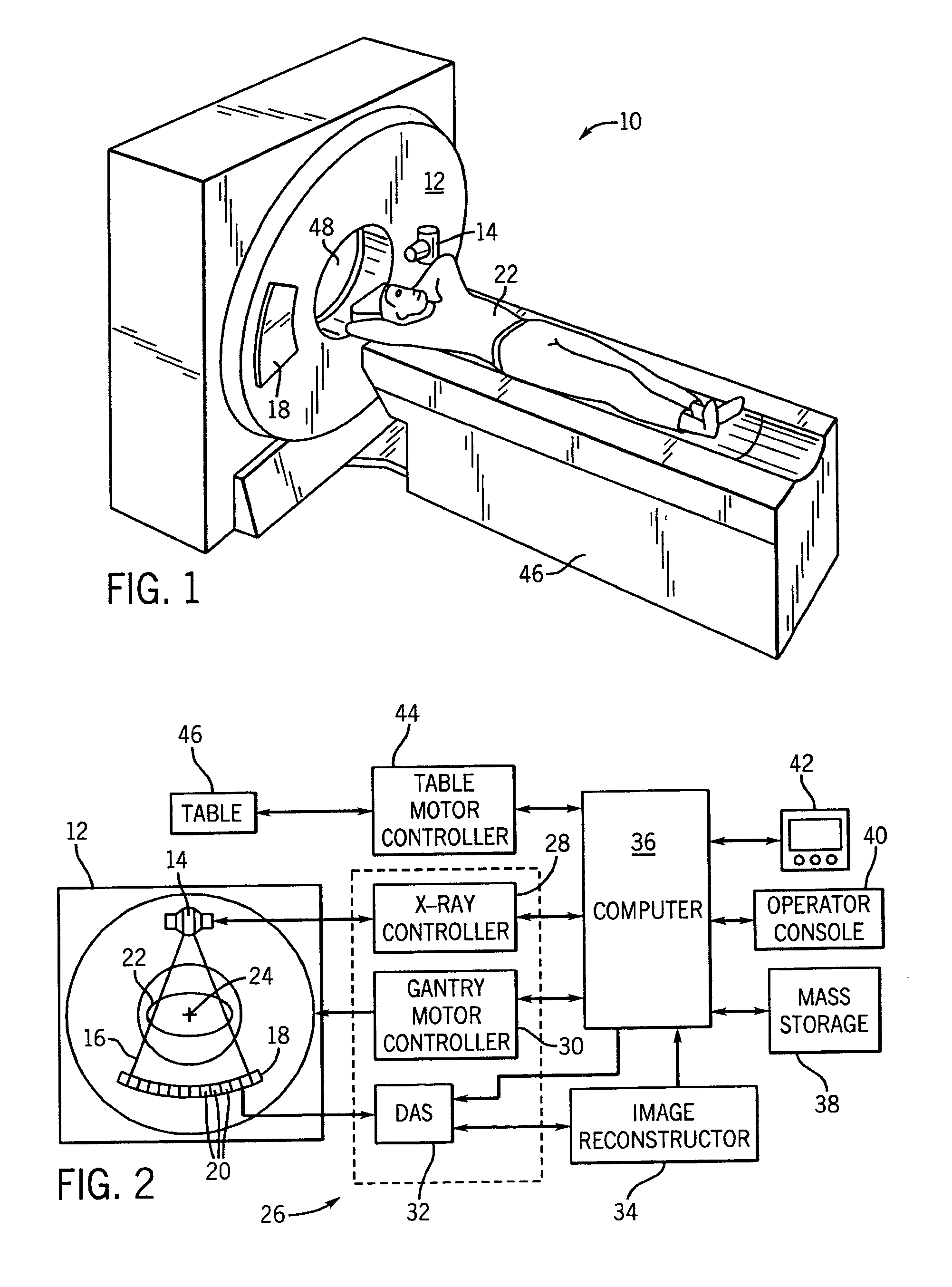
[0028]The operating environment of the present invention is described with respect to a four-slice computed tomography (CT) system. However, it will be appreciated by those skilled in the art that the present invention is equally applicable for use with single-slice or other multi-slice configurations. Moreover, the present invention will be described with respect to the detection and conversion of x-rays. However, one skilled in the art will further appreciate that the present invention is equally applicable for the detection and conversion of other high frequency electromagnetic energy. The present invention will be described with respect to a “third generation” CT scanner, but is equally applicable with other CT systems.

[0029]Referring to FIGS. 1 and 2, a computed tomography (CT) imaging system 10 is shown as including a gantry 12 representative of a “third generation” CT scanner. Gantry 12 has an x-ray source 14 that projects a beam of x-rays 16 toward a detector array 18 on the...


PUM

PropertyMeasurementUnit
thickaaaaaaaaaa
thickaaaaaaaaaa
dimensionaaaaaaaaaa

Abstract

The present invention is directed to an integrated scintillator and collimator array for a CT detector. The integrated scintillator and collimator are fabricated from a manufacturing process or technique whereupon an array of scintillator material is positioned on a tooling base such that a collimator mold housing having a collimator mold therein may be positioned on the block of scintillator material. The block and mold housing are then aligned allowing a collimator mixture to be disposed into the mold. The collimator mixture is then allowed to cure to form an integrated scintillator and collimator.

Description

BACKGROUND OF INVENTION[0001]The present invention relates generally to diagnostic imaging and, more particularly, to an integrated scintillator and collimator and method of manufacturing same.[0002]Typically, in computed tomography (CT) imaging systems, an x-ray source emits a fan-shaped beam toward a subject or object, such as a patient or a piece of luggage. Hereinafter, the terms “subject” and “object” shall include anything capable of being imaged. The beam, after being attenuated by the subject, impinges upon an array of radiation detectors. The intensity of the attenuated beam radiation received at the detector array is typically dependent upon the attenuation of the x-ray beam by the subject. Each detector element of the detector array produces a separate electrical signal indicative of the attenuated beam received by each detector element. The electrical signals are transmitted to a data processing system for analysis which ultimately produces an image.[0003]Generally, the ...

Claims


Application Information

Patent Timeline
Patent Type & Authority Patents(United States)
IPC IPC(8): G21K1/02G01T7/00A61B6/03G01T1/164G01T1/20
CPCG21K1/025G21K1/02G01T1/1648A61B6/032
Inventor HOGE, MICHAEL F.
Owner GENERAL ELECTRIC CO
Why Eureka
Try Eureka