Electromagnetic pathways to eliminate RFID limitations

Inactive Publication Date: 2006-05-18
INT PAPER CO
View PDF12 Cites 48 Cited by
  • Summary
  • Abstract
  • Description
  • Claims
  • Application Information

AI Technical Summary

Benefits of technology

[0013] In accordance with one aspect of the present invention, the present inventor provides an inhanced pathway from a remote RFID reader to a plurality of target tags associated with single or multiple packages, cartons or cases of packaged or unpackaged merchandise, in the form of a supplemental antenna interposed between a location operatively adjacent one or more of individual cases or packages of products which are disposed in stacked or palletized configuration, for example. This supplemental antenna provides for substantially uninterrupted transmission of RFID signals between an RFID reader and an RFID tag irrespective of the presence of RFID-transmission barriers associa

Problems solved by technology

Radio frequencies (RF) are subject to distortion, reflection, weakening, and other adverse effects by such materials as liquids and/or metals, and other environmental effects such as the distance of travel of the RF signal and the presence or absence of RF-blocking or distortion materials between the source of the RF and the receiver thereof (RFID reader, for example).
However, the known limitations on this activity by reason of the presence in the field of the RF of certain materials which hinder the transmission of the signal, for example, strongly adversely affect the accuracy of the detection and reading of RFID tags associated with individual items of merchandise or individual items or clusters of individual items with RFID tags on them.
When packages or containers containing liquids or metals are clustered in a typical shipping pallet configuration or on a retail shelf, then the RFID reader may not recognize all of the RFID tags.
This will r

Method used


Image

  • Electromagnetic pathways to eliminate RFID limitations
  • Electromagnetic pathways to eliminate RFID limitations
  • Electromagnetic pathways to eliminate RFID limitations

Examples


Embodiment Construction

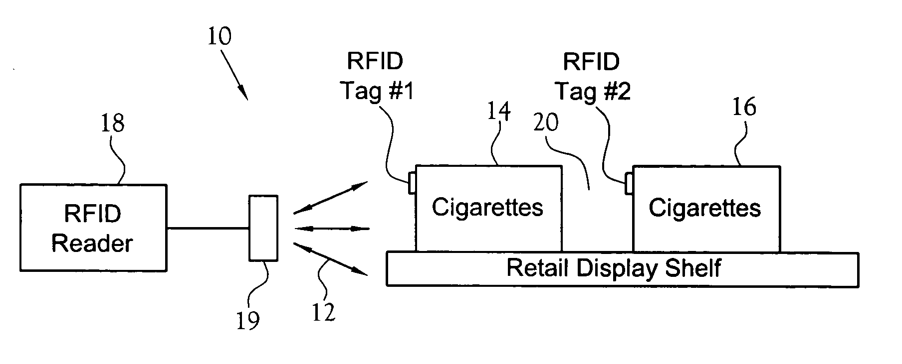
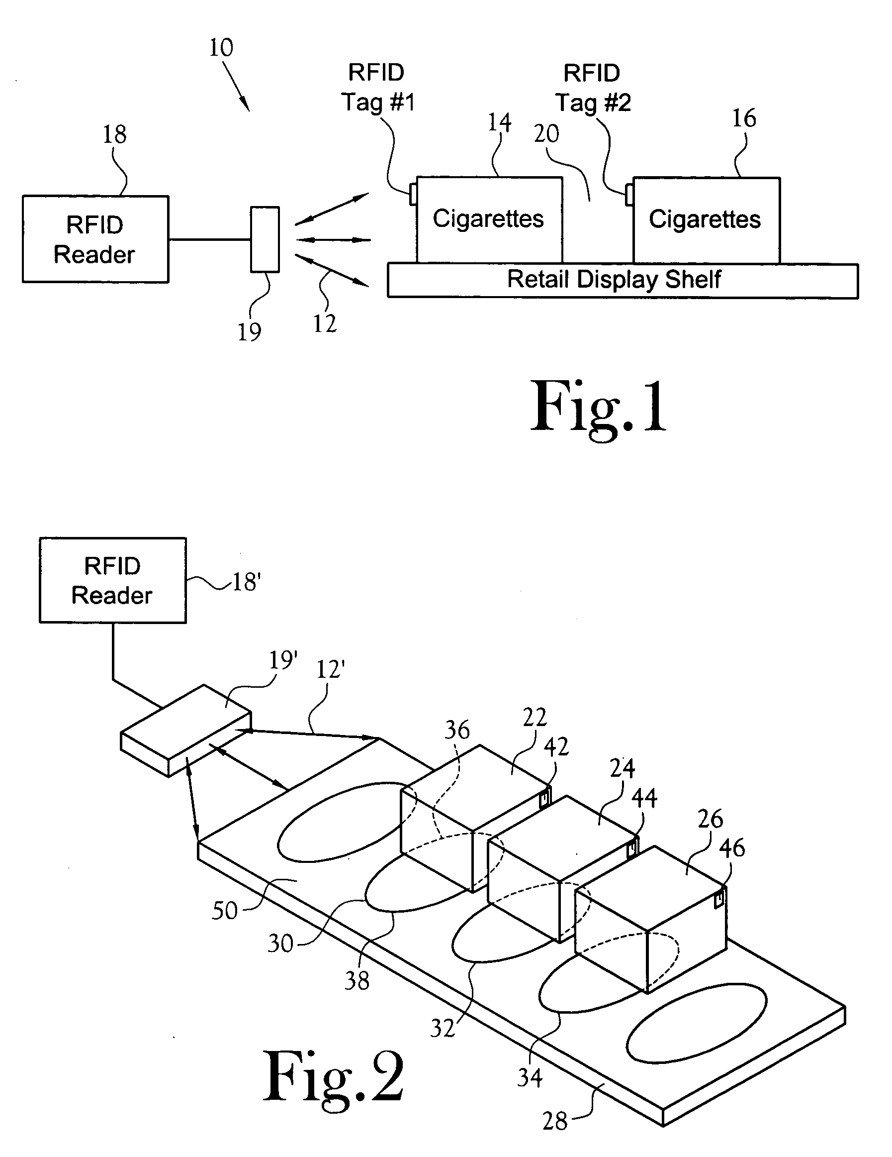
[0020] In FIG. 1, there is depicted a system 10 for the common application of the use of RF signals 12 as a medium for recognizing multiple containers of merchandise stacked on a retail shelf, for example, employing a remote RFID reader 18. In this Figure, there are depicted two RFID-tagged cartons 14 and 16 of cigarettes (known to container metallized foil), the two cartons being aligned with one of the cartons 14 disposed between the other 16 of the cartons and a remote RFID reader 18 having an antenna associated therewith. In this situation, the RFID tag #2 of the second carton will likely not be recognized by the reader due to the metallized foil in the cigarette packages of the first carton 14 blocking or distorting the RF from the reader. In this situation, if the RFID tags are associated with the individual cartons of cigarettes, the reader will consistently recognize RFID tag #1 associated with the first carton 14, but will recognize RFID tag #2 only when there is an air gap...


PUM


Abstract

A system for enhanced substantially simultaneously monitoring multiple aggregated RFID-tagged products comprising an RFID reader disposed remote from said aggregated RFID-tagged products and a supplemental antenna disposed intermediate the RFID reader and the RFID-tagged products. The supplemental antenna includes at least a portion thereof in substantially non-interrupted communication with multiple ones of the RFID tags associated with the RFID-tagged products and at least a portion thereof being in substantially non-interrupted communication with said antenna associated with said RFID reader, whereby said supplemental antenna enhances the transmission of coded information between the reader and the RFID tags associated with the RFID tagged products. A slip sheet having a supplemental antennas associated therewith is disclosed.

Description

CROSS-REFERENCE TO RELATED APPLICATIONS [0001] Not Applicable STATEMENT REGARDING FEDERALLY SPONSORED RESEARCH OR DEVELOPMENT [0002] Not Applicable BACKGROUND OF THE INVENTION [0003] 1. Field of Invention [0004] This invention pertains to electromagnetic identification of tagging of merchandise employing radio frequencies. [0005] More particularly, this invention pertains to a method and apparatus for improving the transmissions of electromagnetic (particularly radio frequency) radiation between an RFID reader and a remote product having an RFID tag associated therewith. [0006] 2. Description of the Related Art [0007] Current practices in inventory management are increasingly employing Radio Frequency Identification (RFID) tags to monitor the progress of merchandise as the individual items or packages move through the supply chain from the manufacturer to the wholesaler to the retailer shelves and / or even to the end user. In this monitoring system, each item or package of merchandis...

Claims


Application Information

Patent Timeline
IPC IPC(8): G08B13/14
CPCG06K7/10178G06K7/10336G06K19/07796
Inventor VAN FLEET, STEVEN ROBERT
Owner INT PAPER CO
Why Eureka
Try Eureka