Radio frequency tag and reader with asymmetric communication bandwidth

a radio frequency tag and communication bandwidth technology, applied in instruments, sensing record carriers, computing, etc., can solve problems such as penetration and reflection, pollute the rf spectrum, and currently available narrow band rfid technologies suffer, and achieve low power and high data rate

Inactive Publication Date: 2006-05-18
PAHLAVAN KOUROSH +1
View PDF0 Cites 47 Cited by
  • Summary
  • Abstract
  • Description
  • Claims
  • Application Information

AI Technical Summary

Benefits of technology

[0025] It is an objective of the present invention to provide a solution to the shortcomings of the currently available RFID designs by combining narrowband and Ultra Wide Band technologies. The system, methods and apparatuses provided by the present invention alleviates these shortcomings by exploiting the benefits of narrow and wide band communication between tags (responders) and readers (interrogators). Using a narrowband link from the reader to the tag warrants for the ability to transmit powerful signals t

Problems solved by technology

Conversely, using an Ultra Wide Band link from the tag to the user warrants for high data rate, low power, massive simultaneous communications between the tags and the readers that are resilient to multipath, penetration and reflection problems that the currently available narrow band RFID

Method used


Image

  • Radio frequency tag and reader with asymmetric communication bandwidth
  • Radio frequency tag and reader with asymmetric communication bandwidth
  • Radio frequency tag and reader with asymmetric communication bandwidth

Examples


Embodiment Construction

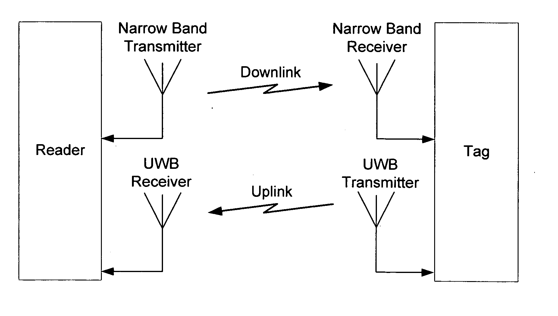
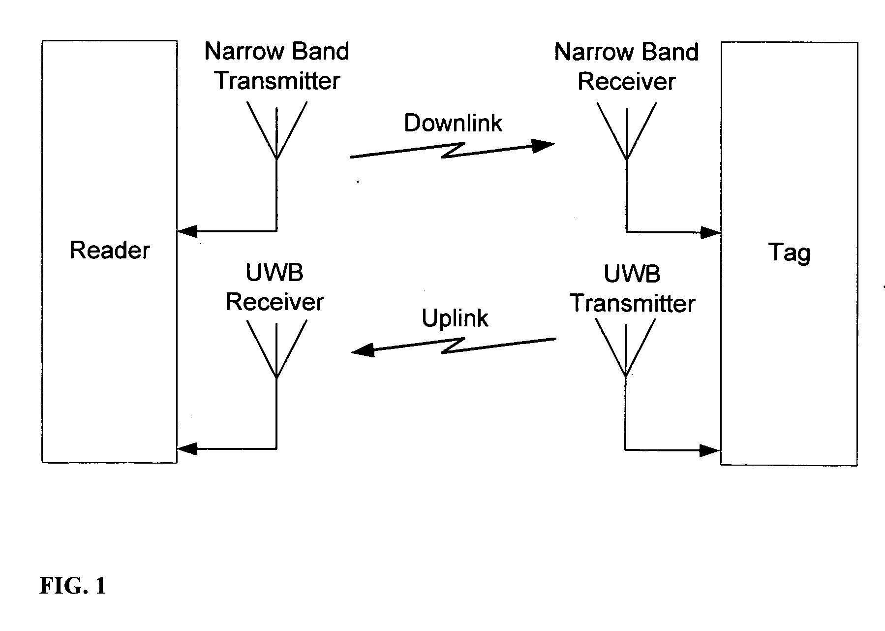
[0036] As illustrated in FIG. 1, the invented reader uses narrow band channels to interrogate the tag. This direction of communication is called a downlink communication. The used band can be in any portion of the spectrum where radio communication is possible. The receivers of these narrowband signals, i.e. the tags, transmit their responses back to the readers in a stream of UWB impulses. The direction of communication in this case is called uplink (see FIG. 1). This means that each reader uses at least a narrowband transmitter and a UWB receiver, while each tag utilizes a UWB transmitter and a narrowband receiver. This asymmetric utilization of the bandwidth, which is the core of this invention, has many benefits, among them: [0037] A UWB transmitter is very simple, low power, easy to design and cheap. This is true for a narrowband receiver as well. By deploying these two simplest combinations of the UWB and narrowband technologies, the tag which is the most critical element of a...


PUM


Abstract

A method and apparatus to overcome fundamental shortcomings in narrow band as well as wide band RFID solutions through offering a hybrid solution that utilizes benefits of narrow band in the downlink direction with the benefits of ultra wide band in the uplink. The invention encompasses a multitude of methods, including an approach to increase the ability to capture electromagnetic energy from the reader.

Description

CROSS-REFERENCE TO RELATED APPLICATIONS [0001]3,516,575Muffitt et al.June 19673,199,424Vinding, J.January 19673,541,995Fathauer, H. GeorgeNovember 19683,689,885Kaplan et al.September 19723,713,148Carelullo et al.January 19736,550,674Neumark, YoramApril 2003STATEMENT REGARDING FEDERALLY SPONSORED RESEARCH OR DEVELOPMENT [0002] N / A BACKGROUND OF THE INVENTION [0003] This invention relates generally to object and inventory identification and control systems and more particularly to a system using inventory identity labels mounted adjacent to inventory items. These labels provide identification information relative to the inventory, wherein the labels are enabled for communication with a computerized inventory management system, and wherein the labels' location and status is known at any time from a remote location. [0004] Radio Frequency Identification (RFID) refers to utilization of RF signals as means of communication between responders, normally tags or similar modules, and interrog...

Claims


Application Information

Patent Timeline
IPC IPC(8): G08B13/14
CPCG06K7/0008G06K7/10306
Inventor PAHLAVAN, KOUROSHHASSANZADEH ESKAFI, FAROKH
Owner PAHLAVAN KOUROSH
Why Eureka
Try Eureka