
Devices and methods for providing wide field magnification

a wide field magnification and device technology, applied in the field of optical devices, can solve problems such as deviation from perfect contiguity of fields, and achieve the effect of limited optical correction

Inactive Publication Date: 2006-05-18
THE RES FOUND OF STATE UNIV OF NEW YORK
View PDF33 Cites 39 Cited by
  • Summary
  • Abstract
  • Description
  • Claims
  • Application Information

AI Technical Summary

Benefits of technology

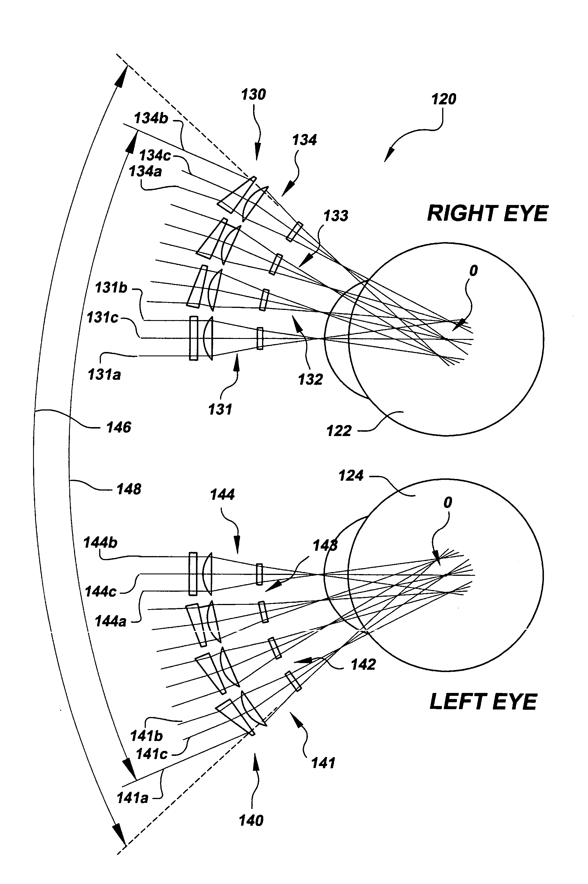
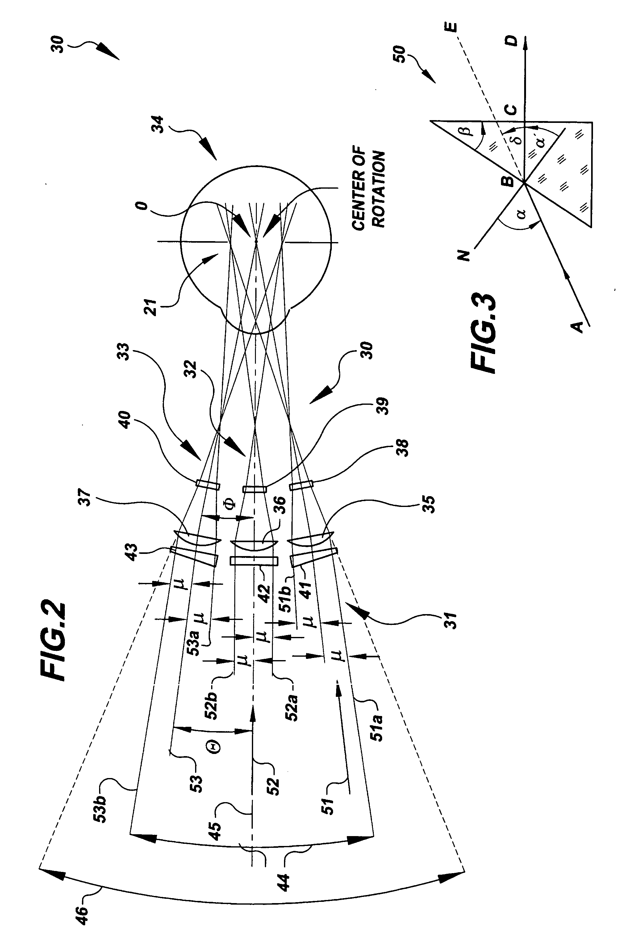
[0011] The present invention provides optic devices that provide wide angular fields of view, even extremely wide angular fields of view, for optical systems such as telescopes, telemicroscopes, and magnifiers. Aspects of the present invention comprise an array of telescopes that may provide more than double the field of view of currently available devices. The inventor employed concepts reminiscent of the Cinerama, that is, the wide screen movie projection system. Introduced in 1952, Cinerama comprised a three-lensed camera that photographed the movie action on triple-width 35-mm film. The movie was then screened with three projectors: one in the center and one at each side of the theater. The three film images become one 146-degree wide image with two degrees of overlap on a curved screen, in what could be referred to as a wide screen “mosaic.” Aspects of the present invention apply this “mosaic” principle to optic devices, somewhat like the compound eyes of insects, to improve the sight of the visually impaired, and others.

Problems solved by technology

Although exact ray tracing demonstrates a seamless contiguity of the composite field of view, several factors, such as vignetting by the field stop, manufacturing tolerances of lenses and mounts, and the precision of alignment of individual telescopes of the array, may result in a deviation from perfect contiguity of fields.

Method used


Image

  • Devices and methods for providing wide field magnification
  • Devices and methods for providing wide field magnification
  • Devices and methods for providing wide field magnification

Examples


Embodiment Construction

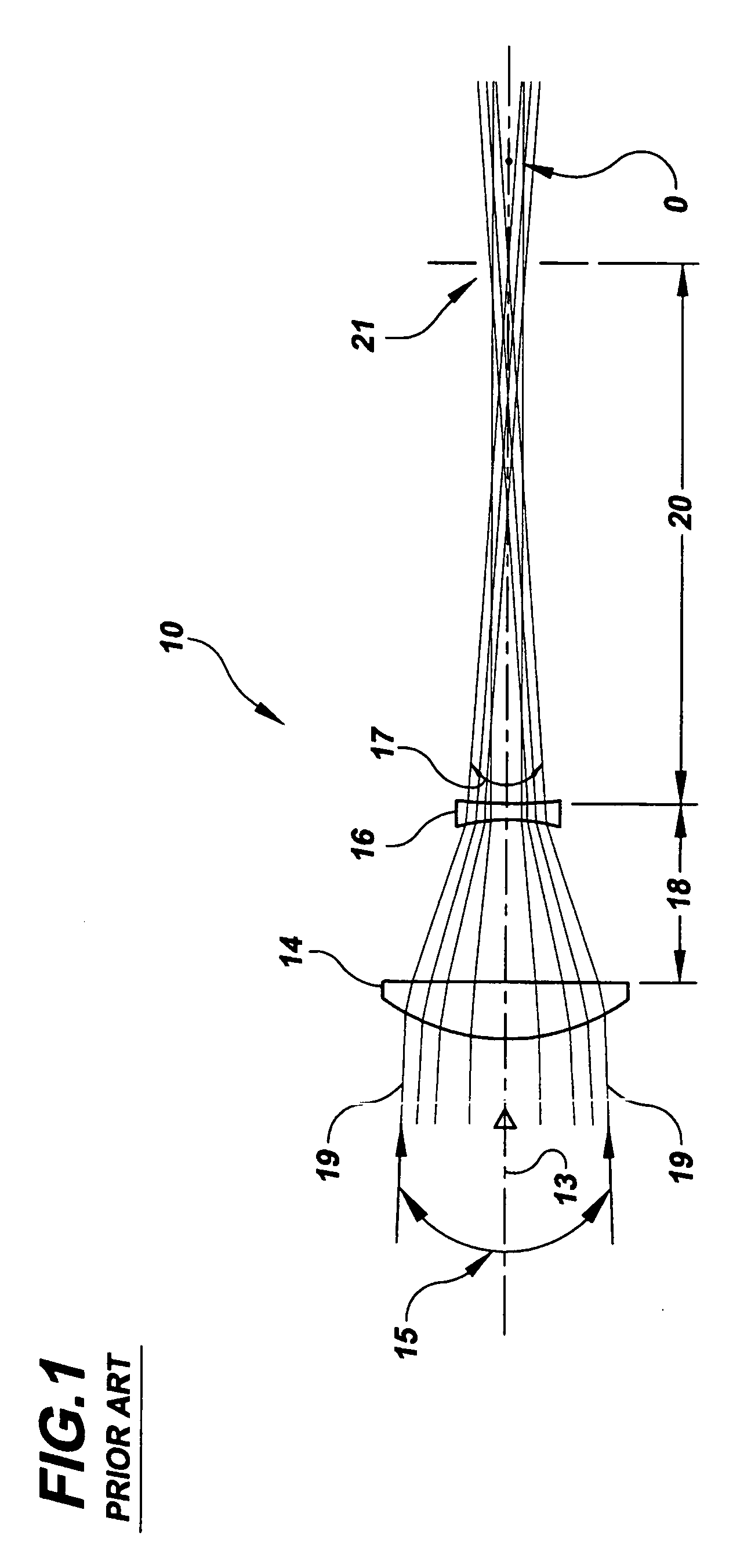
[0039]FIG. 1 is a schematic diagram of a typical prior art lens set 10 coupled to a human eye (not shown) having an iris, that is, an aperture stop, 21. Lens set 10 may be typical of a lens arrangement that may be used for telescopes and telemicroscopes and may be referred to herein as a “telescopic lens set.” As is typical, lens set 10 includes an objective lens 14 and an ocular, or eye, lens 16. As is known in the art, objective lens 14 collects light, as indicated by an axial collimated pencil of light rays 13, from a distant object (not shown), and converges that light to a point or focus at the second focal plane lens (not shown) of the objective. The objective lens 14 also collects collimated pencils of light from both edges of the FOV 17. Light pencils 19 are each focused as points in the second focal plane of objective lens 14. Ocular lens 16 intercepts the converging pencils of light before they reach the focal plane of objective 14 and recollimates the pencils with magnifi...


PUM


Abstract

Optical devices and methods for providing wide field magnification to assist the visually impaired, and others, are provided. The optical device includes a plurality of telescopic lens sets, for example, a plurality of telescopes, each telescopic lens set including an objective lens and an ocular lens, and a plurality of refracting optical elements, for example, prisms, positioned in front of at least some of the objective lenses. The refracting optical elements are adapted to at least partially redirect light rays toward at least some of the objective lenses to provide wider fields of view, for example, a wider contiguous field of view. Aspects of the invention can provide fields of view up to 40 degrees or more. These wider fields of view can greatly enhance the visual acuity of the visually impaired, as well as provide wider fields of view for non-corrective purposes, such as for field observations.

Description

TECHNICAL FIELD [0001] The present invention generally relates to optical devices that magnify distant and near objects to assist normally sighted and visually impaired users. More particularly, the present invention relates to optical devices having a plurality of telescopic lens sets that provide an enlarged filed of view for distance viewing and near visual tasks, such as, reading. BACKGROUND INFORMATION [0002] Prior art optical devices include many types of magnifiers, telescopes, and telemicroscopes prescribed to assist the normally sighted and the visually impaired, for example, people with poor vision, to see objects at a distance and close up. Almost all of the existing telescopes designed for the visually impaired are conventional Galilean-type or terrestrial Keplerian-type telescopes. Typically, these conventional telescopes have restricted fields of view that depend mainly on their magnification, degree of optical correction, and the corresponding complexity of their opti...

Claims


Application Information

Patent Timeline
Patent Type & Authority Applications(United States)
IPC IPC(8): G02B1/00G02B23/00
CPCG02B3/0037G02B13/06G02B23/02G02C7/088G02B3/0006G02C7/08
Inventor KATZ, MILTON
Owner THE RES FOUND OF STATE UNIV OF NEW YORK
Learn More