Supercharge Your Innovation With Domain-Expert AI Agents!

Thin film magnetic head structure, method of making the same and thin film magnetic head

a thin film magnetic head and magnetic head technology, applied in the direction of heads with metal sheet cores, data recording, instruments, etc., can solve the problems of data erased beforehand on a hard disk, pole erasure, etc., and achieve the effect of improving the recording density

Active Publication Date: 2006-05-18
HEADWAY TECH INC
View PDF9 Cites 8 Cited by
  • Summary
  • Abstract
  • Description
  • Claims
  • Application Information

AI Technical Summary

Benefits of technology

[0012] In the conventional PMRs such as the thin-film magnetic head 400, however, even when the direction of magnetization ms is oriented so as to extend along the ABS 403, the direction of remnant magnetization mr inside the main magnetic pole layer 402 after completion of writing is oriented toward the ABS 403 side and thus faces a different direction than the magnetization ms. (The direction different from that extending along the ABS will be referred to as “different direction” in the following.) Therefore, when such a PMR writes data, leakage magnetic fluxes due to the remnant magnetization mr may erase data already written on a hard disk or weaken signals of written data even though no write current is flowing.
[0013] In order to overcome the problem mentioned above, it is an object of the present invention to provide a thin-film magnetic head structure which can manufacture a thin-film magnetic head comprising a structure capable of preventing the pole erasure from occurring while improving the recording density, a method of manufacturing the same, and a thin-film magnetic head.

Problems solved by technology

However, the conventional PMRs have been problematic in that they cause a phenomenon known as pole erasure by which data recorded beforehand on a hard disk is erased when information is further recorded at a high density.

Method used


Image

  • Thin film magnetic head structure, method of making the same and thin film magnetic head
  • Thin film magnetic head structure, method of making the same and thin film magnetic head
  • Thin film magnetic head structure, method of making the same and thin film magnetic head

Examples


first embodiment

[0070] Configuration of Thin-Film Magnetic Head Structure

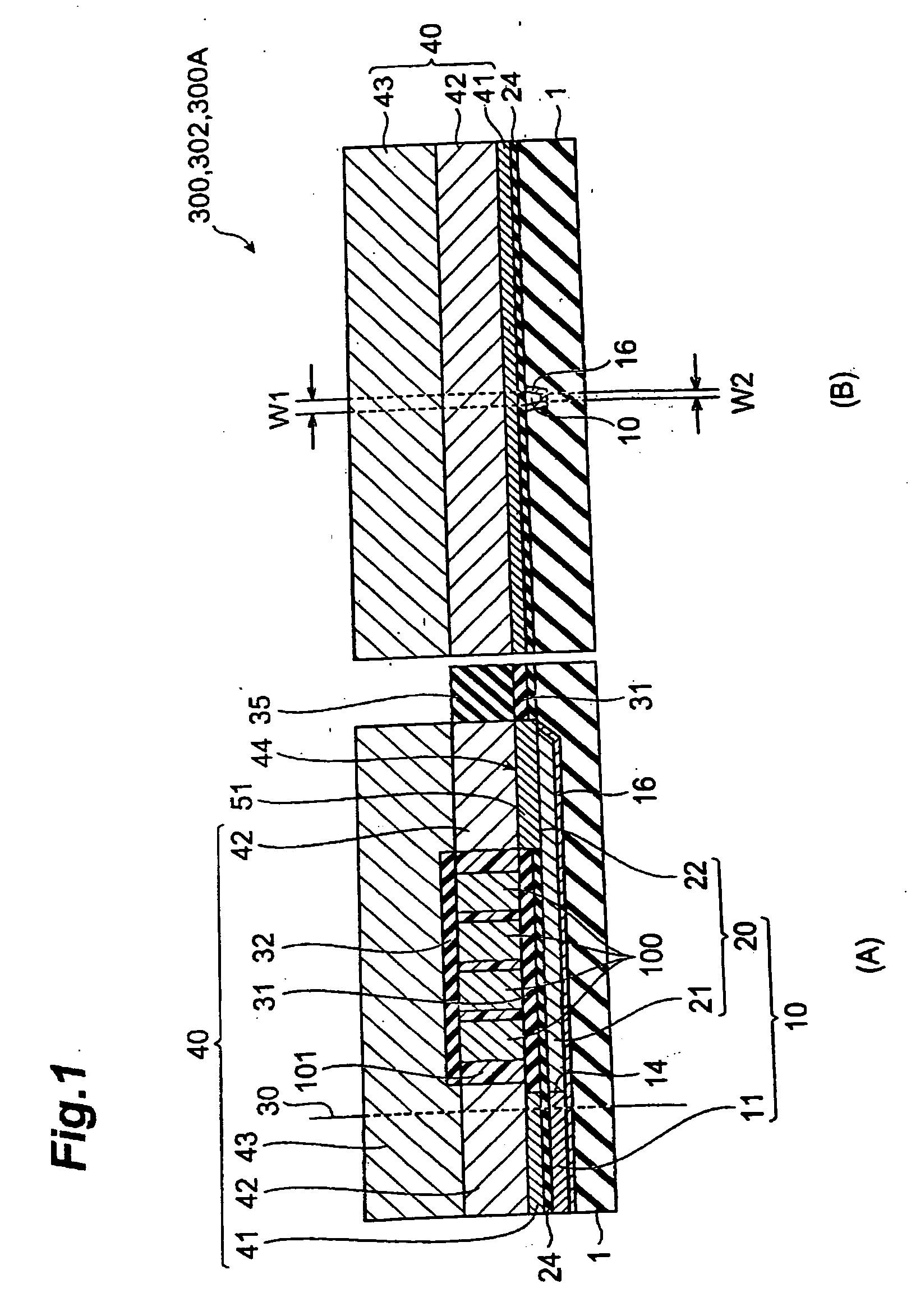
[0071] First, with reference to FIGS. 1 to 6, the configuration of the thin-film magnetic head structure in accordance with the first embodiment of the present invention will be explained. FIG. 1 is a sectional view of a thin-film magnetic head structure 300 in accordance with the first embodiment of the present invention, in which (A) is a sectional view taken along a direction intersecting a thin-film coil, and (B) is a sectional view showing the ABS when cut at the ABS.

[0072] The thin-film magnetic head structure 300 in accordance with the first embodiment has a configuration adapted to manufacture a magnetic head for perpendicular recording. The thin-film magnetic head structure 300 is formed on a substrate which is not depicted, and yields a thin-film magnetic head in the present invention when cut at an ABS 30 which is a medium-opposing surface opposing a recording medium (hard disk).

[0073] The thin-film magnetic head...

second embodiment

[0134] With reference to FIGS. 16(A) and (B), the thin-film magnetic head structure in accordance with the second embodiment of the present invention will be explained. FIG. 16 is a sectional view of the thin-film magnetic head structure 310 in accordance with the second embodiment of the present invention, in which (A) is a sectional view taken along a direction intersecting a thin-film coil, and (B) is a sectional view showing the ABS when cut at the ABS.

[0135] Configuration of Thin-Film Magnetic Head Structure

[0136] The thin-film magnetic head structure 310 in accordance with the second embodiment is the same as the above-mentioned thin-film magnetic head structure 300 except that it includes a nonmagnetic film 61. The following explanation relates to their difference while omitting or simplifying descriptions concerning their common points.

[0137] The nonmagnetic film 61 is formed in a portion of the yoke magnetic pole part 20 other than its surface on the thin-film coil 100 s...

modified example 1

[0143] The manufacturing process mentioned above can be modified as in the first embodiment. Namely, after forming the first shield part 41 and the back magnetic pole layer 51, the whole upper face of the substrate is subjected to CMP, and then the thin-film coil 100 is formed by way of the insulating layer 31 earlier than the second shield part 42. Next, the photoresist 101 is formed so as to cover the thin-film coil 100. Further, the second shield part 42 is formed so as to cover the thin-film coil 100 and the photoresist 101, and connect with the first shield part 41 and the back magnetic pole layer 51. This yields a thin-film magnetic head structure 311 including a write shield layer 40 comprising the first shield part 41 and second shield part 42 without the third shield part 43 as shown in FIGS. 20(A) and (B).

[0144] This thin-film magnetic head structure 311 has the same configuration as with the thin-film magnetic head structure 310 except that it lacks the third shield part...


PUM

PropertyMeasurementUnit
Lengthaaaaaaaaaa
Sizeaaaaaaaaaa
Widthaaaaaaaaaa

Abstract

A thin-film magnetic head structure has a configuration adapted to manufacture a thin-film magnetic head configured such that a main magnetic pole layer including a magnetic pole end part on a side of a medium-opposing surface opposing a recording medium, a write shield layer opposing the magnetic pole end part so as to form a recording gap layer on the medium-opposing surface side, and a thin-film coil wound about the write shield layer or main magnetic pole layer are laminated. The main magnetic pole layer has an end face joint structure where respective end faces of the magnetic pole end part and a yoke magnetic pole part having a size greater than that of the magnetic pole end part are joined to each other, and a surface with a flat structure on a side closer to the thin-film coil.

Description

BACKGROUND OF THE INVENTION [0001] 1. Field of the Invention [0002] The present invention relates to a thin-film magnetic head structure for manufacturing a thin-film magnetic head which performs magnetic recording operations by perpendicular recording, a method of manufacturing the same, and a thin-film magnetic head. [0003] 2. Related Background Art [0004] In recent years, the areal density in hard disk drives has been increasing remarkably. Recently, the areal density in hard disk drives has reached 160 to 200 GB / platter in particular, and is about to increase further. Accordingly, thin-film magnetic heads have been required to improve their performances. [0005] In terms of recording schemes, thin-film magnetic heads can roughly be divided into those for longitudinal recording in which information is recorded in a (longitudinal) direction of a recording surface of a hard disk (recording medium) and those for perpendicular recording in which data is recorded while the direction of...

Claims


Application Information

Patent Timeline
IPC IPC(8): G11B5/147
CPCG11B5/1278G11B5/3116G11B5/3163Y10T29/49048Y10T29/49046Y10T29/49044Y10T29/49052Y10T29/49043
Inventor SASAKI, YOSHITAKAARAKI, HIRONORITANEMURA, SHIGEKIITO, HIROYUKIGUAN, LIJIE
Owner HEADWAY TECH INC
Features
  • R&D
  • Intellectual Property
  • Life Sciences
  • Materials
  • Tech Scout
  • Unparalleled Data Quality
  • Higher Quality Content
  • 60% Fewer Hallucinations
Learn More