
System for analyzing quality of communication sections

a communication section and quality analysis technology, applied in the field of systems for analyzing the quality of communication sections, can solve the problems of substantial cost, voice quality degradation, and large load on the ip network, and achieve the effect of reducing the number of devices used

Inactive Publication Date: 2006-05-18
FUJITSU LTD
View PDF4 Cites 53 Cited by
  • Summary
  • Abstract
  • Description
  • Claims
  • Application Information

AI Technical Summary

Benefits of technology

[0025] An object of the present invention is to provide a technique for reducing the number of devices used for specifying a communication section assumed to cause quality degradation as compared with the prior art.

Problems solved by technology

However, the conventional techniques shown in FIGS. 33 and 34 have the following problems.
This leads to a problem of substantial costs.
Fourth, in the system shown in FIG. 33, the analysis device collects signal logs from plural monitoring devices, and load on the IP network is substantial.
Fifth, in the system shown in FIG. 34, if the number of alarms received by the analysis device is small, it is difficult to specify a “defective section” causing voice quality degradation.
Sixth, in the system shown in FIG. 34, even when the number of alarms is large, if the call path has a deviation, it is difficult to specify a “defective section” causing voice quality degradation.
Seventh, in the system shown in FIG. 34, in the case of calling via a VOIP network that does not issue alarm notifications, for example, via another VOIP carrier network, it is impossible to determine whether a “defective section” exists in its own network or a “defective section” exists in the other VOIP carrier network.
Eighth, in the system shown in FIG. 34, if the number of alarm notifications increases, the load on the network accordingly increases, leading to a problem of alarm induction.

Method used


Image

  • System for analyzing quality of communication sections
  • System for analyzing quality of communication sections
  • System for analyzing quality of communication sections

Examples


Embodiment Construction

[0069] Hereinafter, preferred embodiments for carrying out the present invention will be described with reference to the drawings. The structures of embodiments merely represent examples, and the present invention is not limited to the structures of the embodiments.

[0070]

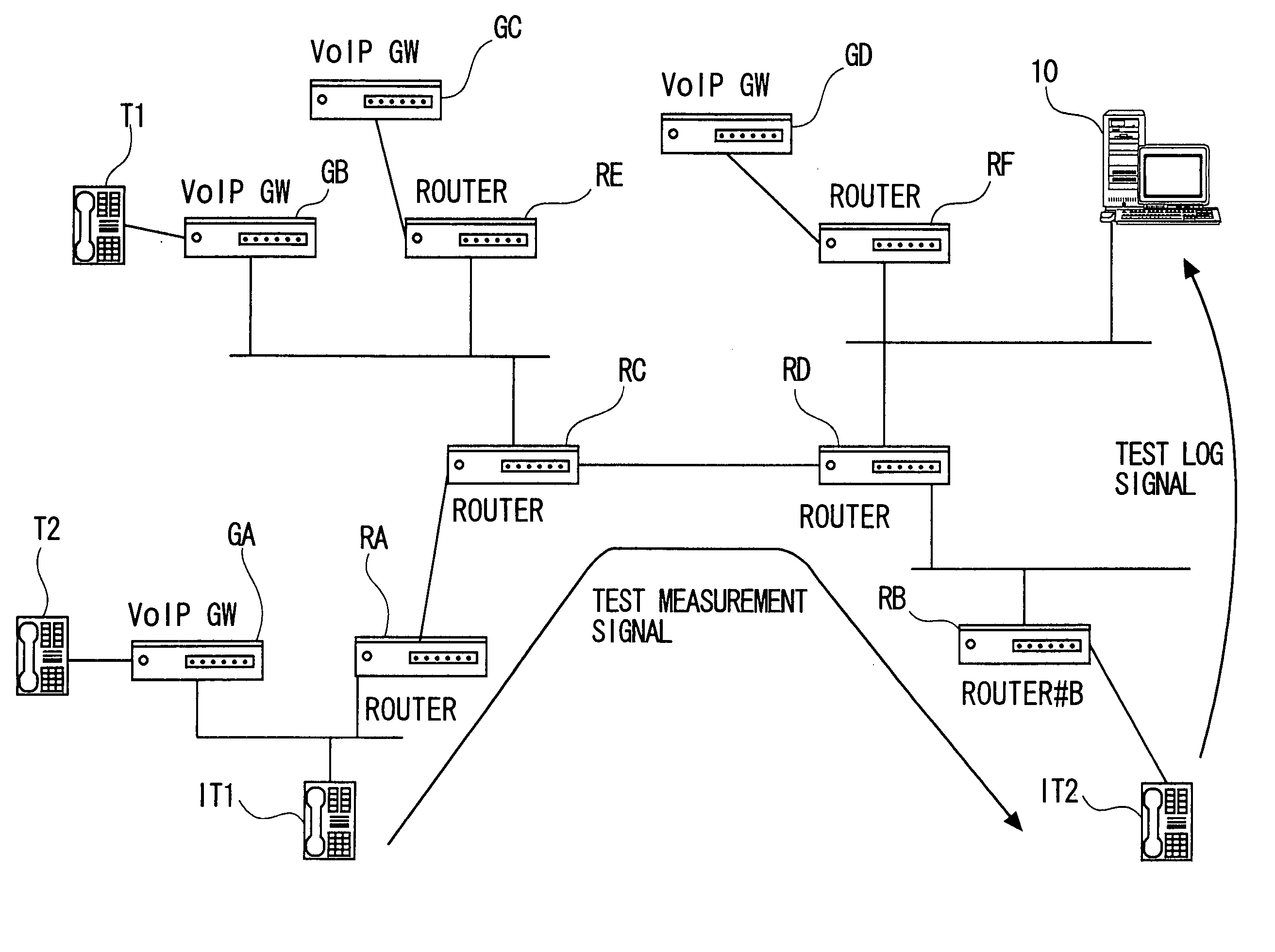
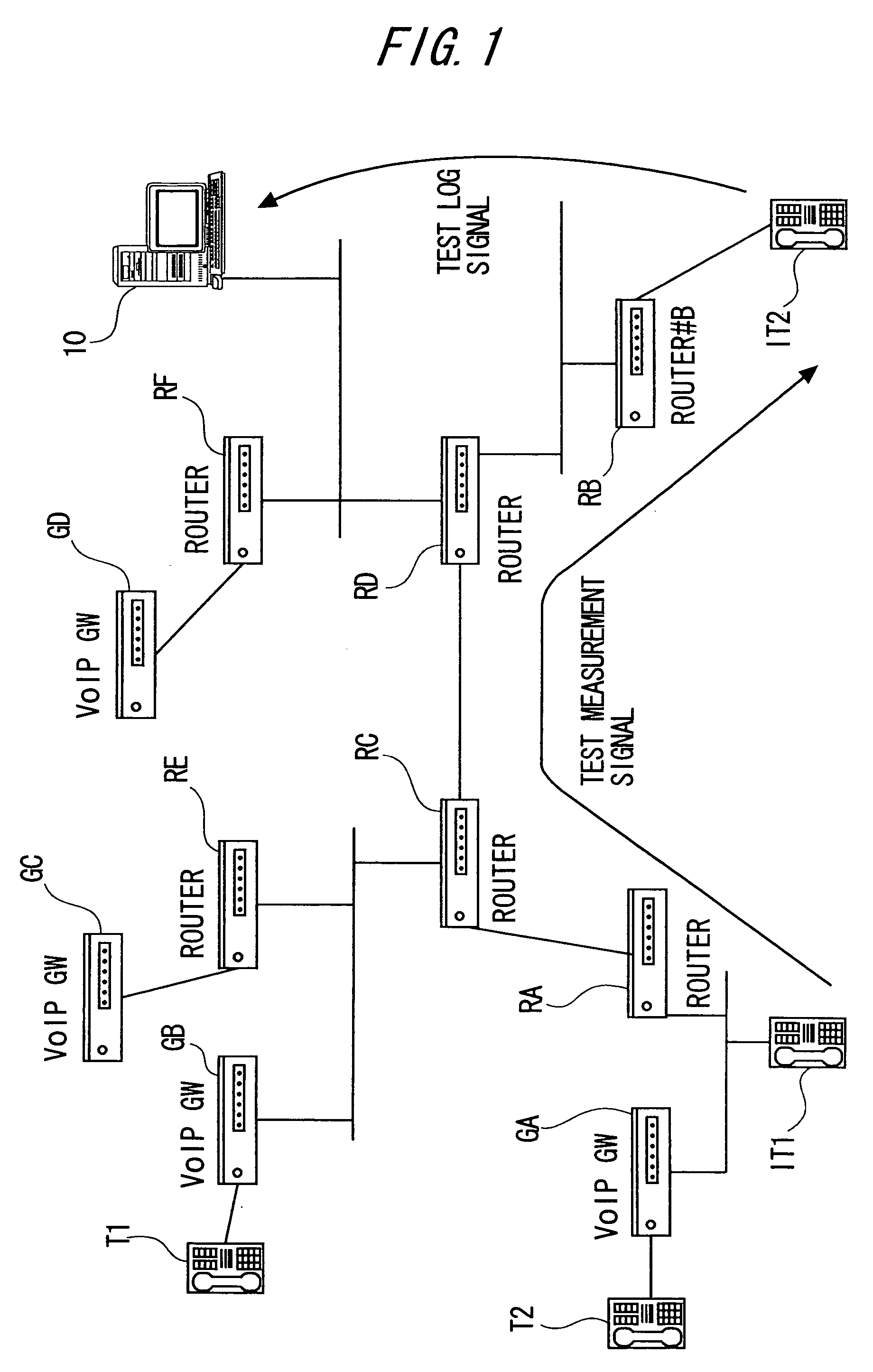
[0071]FIG. 1 shows an overall structure example of a quality degradation section detection system in communication paths according to the present invention. The system shown in FIG. 1 includes plural routers constituting an IP network, VOIP gateways installed at borders between the IP network and circuit switch networks (e.g., PSTN), telephones functioning as communication terminals connected to the VoIP gateway via the circuit switch network, an IP telephone connected to a LAN or router constituting the IP network, and an analysis device connected to the IP network.

[0072] The IP network shown in FIG. 1 includes routers RA, RB, RC, RD, RE and RF connected to VoIP gateways GA to GD. Then, telephone Tl and T2 are co...


PUM


Abstract

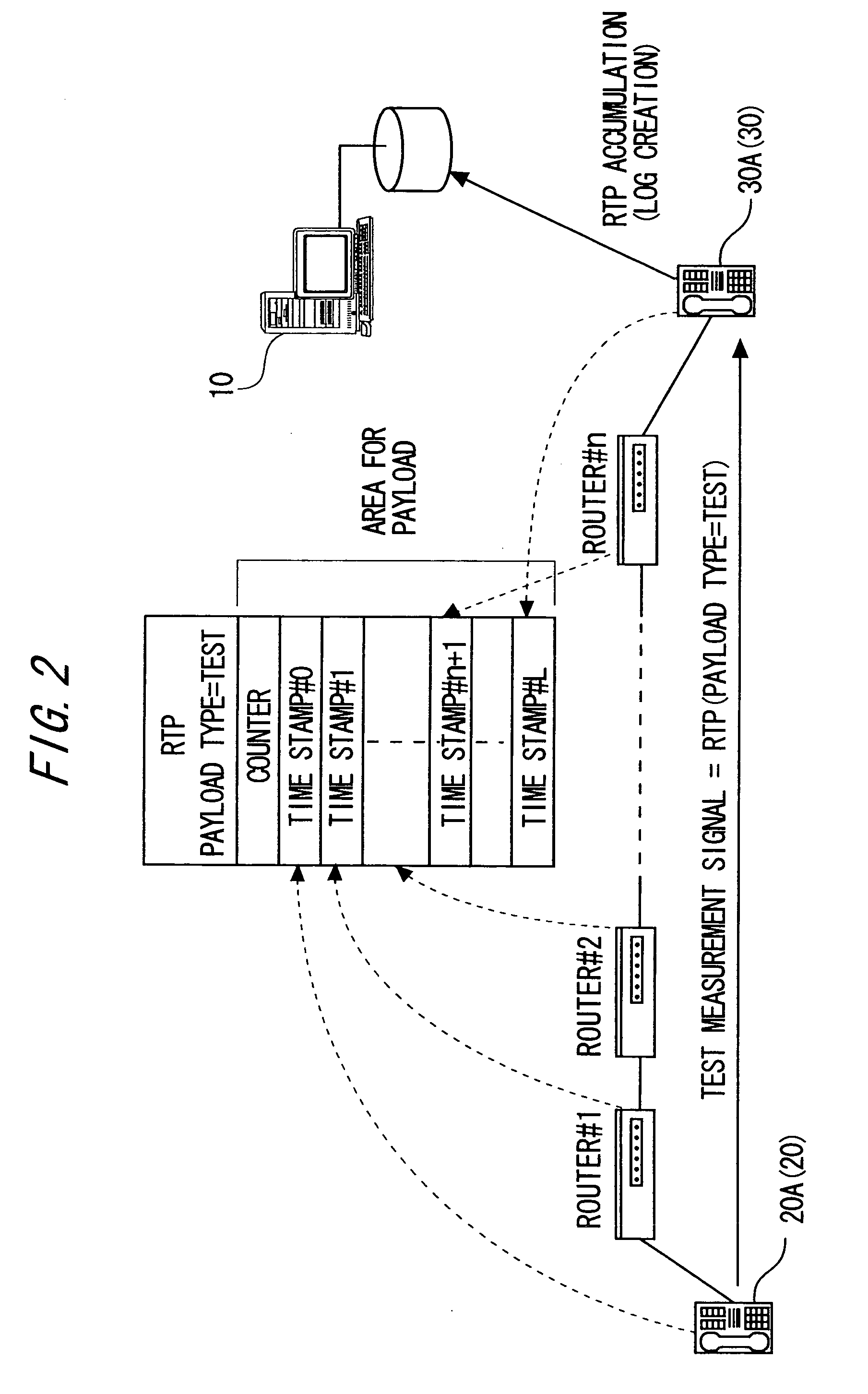
A system for analyzing quality of communication sections includes a transmission device transmitting a test measurement signal, a reception device receiving the test measurement signal, relay devices each located on a transmission path of the test measurement signal between the transmission device and the reception device, setting a relay time in the test measurement signal when relaying the test measurement signal toward the reception device, and an analysis device including a reception unit receiving two or more relay time measurement results of the relay devices, each of which is obtained by the reception device when transmission / reception of the test measurement signal is performed two or more times by the transmission device and the reception device, a calculation unit calculating a quality index value of a communication section between the relay devices based on the relay time measurement results, and an output unit outputting the communication quality index value of the communication section.

Description

CROSS-REFERENCE TO RELATED APPLICATION [0001] This is a continuation of Application PCT / JP2003 / 009934, filed on Aug. 5, 2003, now pending, the contents of which are herein wholly incorporated by reference.BACKGROUND OF THE INVENTION [0002] 1. Field of the Invention [0003] The present invention relates to a technique for detecting a section (interval) assumed to cause communication quality degradation in a communication path. The present invention relates, for example, to a technique for detecting a section causing voice (speech) quality degradation on a voice path of VOIP (Voice over IP). [0004] 2. Description of the Related Art [0005] In recent years, there is known a technology for transferring voice information using an IP (Internet Protocol) network based on a VoIP technology to realize a call (communication) between terminals (referred to as “Internet Telephony” technology). According to this technology, as shown in FIGS. 33 and 34 for example, a VOIP gateway (VOIP GW) for perf...

Claims


Application Information

Patent Timeline
IPC IPC(8): H04J1/16H04J3/14H04L12/26H04L12/28H04L12/56H04L12/66
CPCH04J3/14H04L12/2697H04L12/2854H04L12/66H04L43/50H04L47/10H04L47/115
Inventor KAKO, MASAHARU
Owner FUJITSU LTD
Learn More