Optical network for bi-directional wireless communication

a bi-directional wireless communication and optical network technology, applied in the field of optical networks, can solve the problems of difficult to obtain a suffer from poor reception efficiency, and achieve the effect of sufficient power margin for signals

Inactive Publication Date: 2006-05-18
SAMSUNG ELECTRONICS CO LTD
View PDF13 Cites 102 Cited by
  • Summary
  • Abstract
  • Description
  • Claims
  • Application Information

AI Technical Summary

Benefits of technology

The present invention solves issues with existing optical networks by adding a remote antenna that reduces power loss during signal transmission. This ensures enough power remains for reliable communication.

Problems solved by technology

This patent describes two types of optical networks used for relaying radio signals: one uses a single electro-absorption modulator (EAM), while the other utilizes multiple EAMs with different configurations. However, there are limitations when processing both uplink and downlink optical signals with a single EAM due to reduced reception efficiency and difficulty in achieving adequate power margin. Additionally, the use of multiple EAMs can lead to increased complexity and cost. Therefore, this technical problem addresses how to improve the performance and reliability of optical networks for relaying radio signals more efficiently without compromising signal quality.

Method used


Image

  • Optical network for bi-directional wireless communication
  • Optical network for bi-directional wireless communication
  • Optical network for bi-directional wireless communication

Examples


Embodiment Construction

[0023] Hereinafter, embodiments of the present invention will be described with reference to the accompanying drawings. For the purposes of clarity and simplicity, a detailed description of known functions and configurations incorporated herein will be omitted as it may make the subject matter of the present invention unclear.

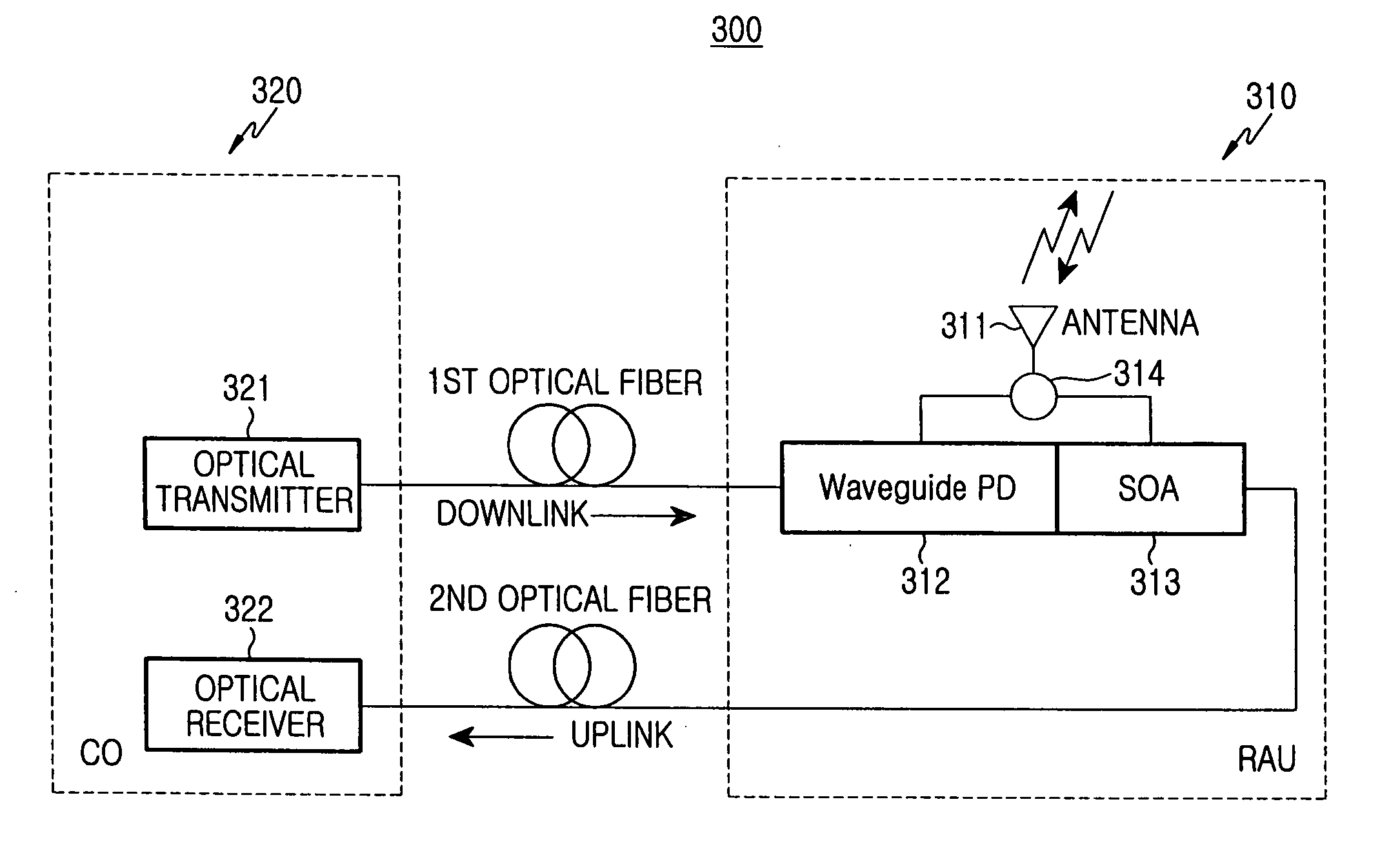
[0024]FIG. 3 illustrates a bi-directional optical network for relaying radio signals according to one embodiment of the present invention. As shown, the optical network 300 according to the present invention includes a base station 320 for generating downlink optical signals and detecting uplink optical signals, and a remote antenna unit 310 for transmitting the downlink radio signals over the air and receiving uplink radio signals from the outside of the unit 310. The remote antenna unit 310 converts the received uplink radio signals into the uplink optical signals and outputs the uplink optical signals to the base station 320. The optical network 300 further...


PUM


Abstract

An optical network for bi-directional communication includes: a base station for generating downlink optical signals and detecting uplink optical signals; and a remote antenna unit for transmitting the downlink optical signals and generating the uplink optical signals to the base station; wherein the remote antenna includes: an optical detector for converting the downlink optical signals into downlink radio signals; an antenna for transmitting the downlink radio signals to outside thereof, and receiving the uplink radio signals in wireless communication; a semiconductor optical amplifier for converting the uplink radio signals into the uplink optical signals to output the uplink optical signals to the base station; and a circulating device having a plurality of ports, each of which is connected to the antenna, the optical detector, and the semiconductor optical amplifier, respectively.

Description


Claims


Application Information

Patent Timeline
Owner SAMSUNG ELECTRONICS CO LTD
Why Eureka
Try Eureka