
Ubiquitous connectivity and control system for remote locations

a remote location, connectivity technology, applied in the field of remote monitoring and control system, can solve the problems of inability to maintain the full functions of the appliance year round, inability to meet the needs of users, etc., to achieve the effect of reducing limitations, immobility, and inopportunities

Inactive Publication Date: 2006-05-18
UBIQUITOUS CONNECTIVITY
View PDF41 Cites 58 Cited by
  • Summary
  • Abstract
  • Description
  • Claims
  • Application Information

AI Technical Summary

Benefits of technology

[0012] The present invention uses an on-demand digital, private, and direct communications interface to overcome the shortcomings and limitations of current communications interfacing. A digital, private, and direct-connect remote controller provides instant wireless connectivity to the home from anywhere in the world without dialing a number or waiting for a number of tones to send a command or to know the status of conditions in the home; provides silent and constant direct two-way communication privately and globally, with the home for control and monitoring of key functions; eliminates limitations, immobility, and inopportunities to connect, monitor and control the home, globally; can be configured to interface with many existing and future home automation systems and technologies; provides instant ubiquitous control for the end-user; and, if so desired, eliminates the need for the PC, modems and interconnected wiring.
[0013] The digital private direct connect controller allows the end-user to finally realize true global connectivity to and control of the home.

Problems solved by technology

Also, owners of businesses generally have their place of business remote from their residence.
Where the building is in a volatile climatic region, it is not always feasible to maintain the full functions of the appliances year round.
The home control industry has taken steps toward ubiquitous connectivity and control over the years, but these steps have fallen short until now.
While an advance in connectivity, mobile Internet connectivity, like its predecessors, is not without significant challenges, especially with mobility and convenience.
The X10 system, like most power line carrier technologies, is characteristically confined to operation within a very limited area, such as within a single building.
While such systems allow users to exercise control of their facilities remotely, they are not as user friendly and often use tones or cryptic, hard-to-understand, digitized voice prompts.

Method used


Image

  • Ubiquitous connectivity and control system for remote locations
  • Ubiquitous connectivity and control system for remote locations
  • Ubiquitous connectivity and control system for remote locations

Examples


Embodiment Construction

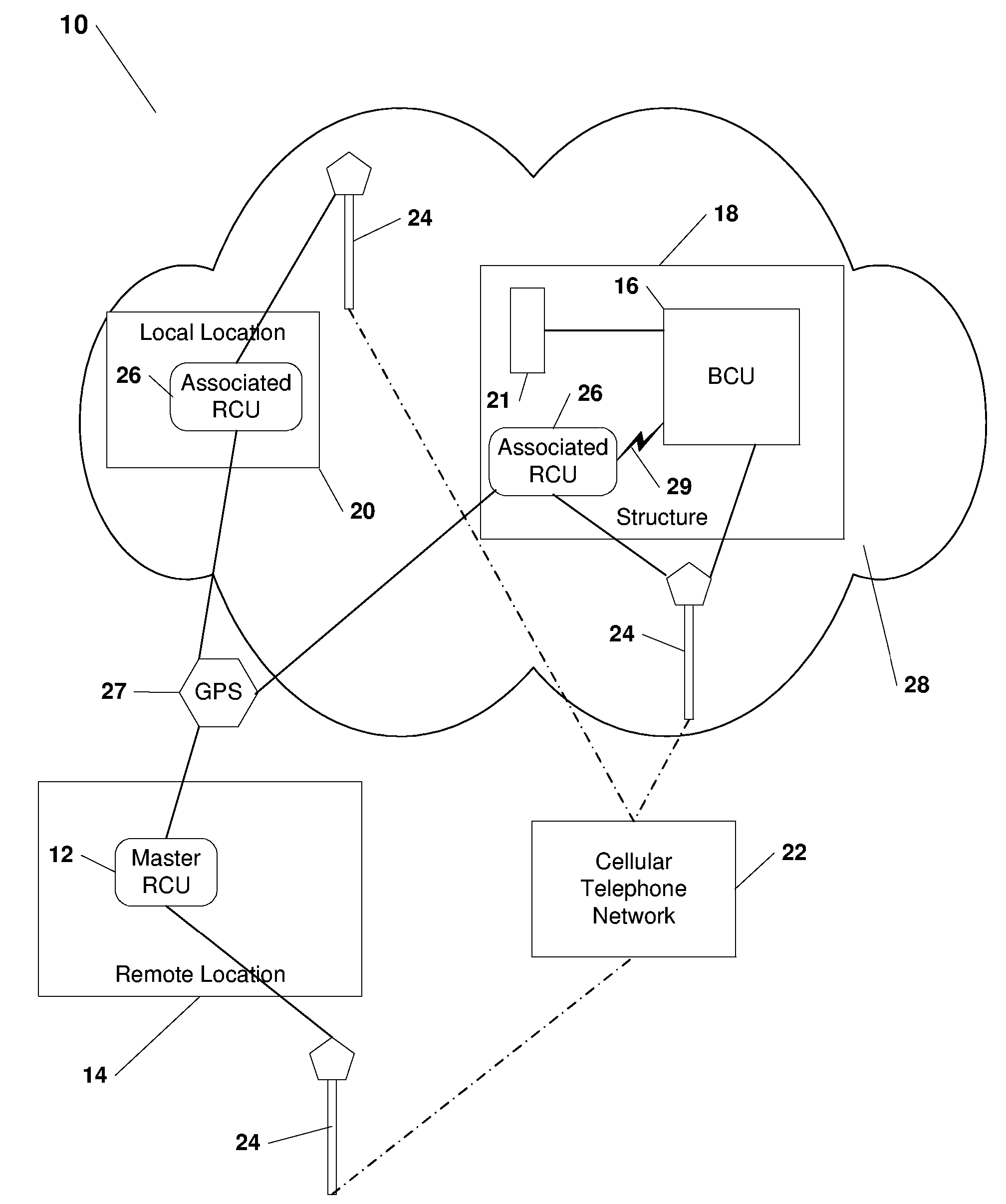
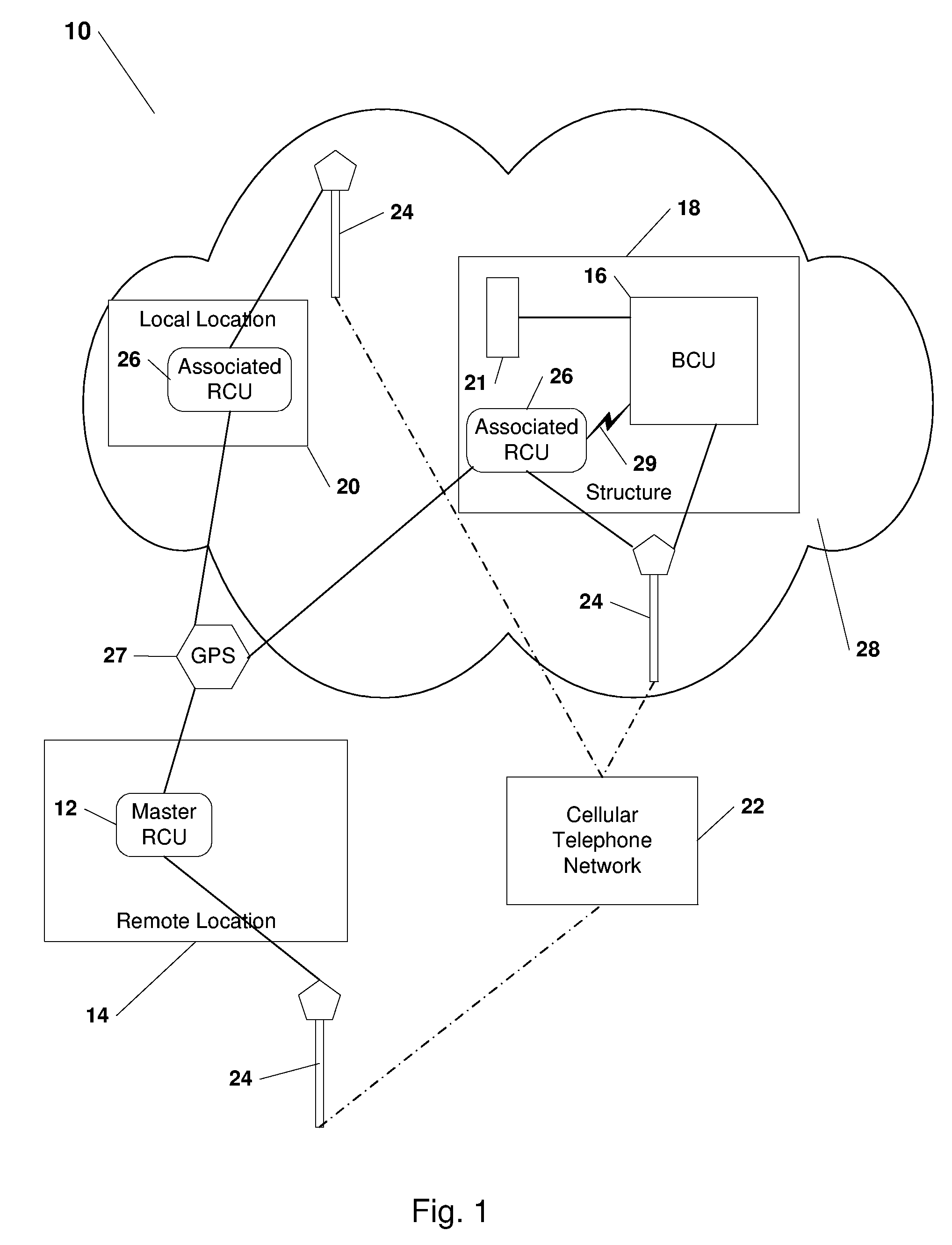
[0020] Referring to the drawings, FIG. 1 illustrates a ubiquitous connectivity and control system 10 wherein a master remote control unit 12 at a geographically remote location 14 on demand interfaces with a base control unit 16 in a structure 18 to monitor and control associated devices 21 thereat through a short message and / or the data bearer cellular telephone network 22 including control towers 24. The system 10 further includes associated control units 26 that are enabled by the base control unit 16 to undertake select monitoring and controlling activities in a proximate area 28. Associated control units 26 and the master control unit 12 utilize the global position network 27 and / or the cellular telephone network 22 and towers 24 in order to determine their geographical locations 14, 20 and report this information back to the base control unit 16 using the short message and / or data bearer services of the cellular telephone network 22 and control towers 24.

[0021] Referring to F...


PUM


Abstract

A thermostat control system for monitoring and controlling environmental characteristics of a building includes a base station unit and a remote access unit continuously interfacing through instant wireless private direct connectivity. The system also includes a plurality of sensors that measure the environmental characteristics and provide the thermostat unit with the measurements.

Description

RELATED APPLICATION [0001] This application is a divisional of U.S. application Ser. No. 11 / 160,006, filed Jun. 6, 2005, which claims the benefit of U.S. Provisional Application No. 60 / 522,887, filed Nov. 18, 2004, in the name of Charles Shamoon and entitled “Ubiquitous Connectivity and Control System for Remote Locations”.FIELD OF THE INVENTION [0002] The present invention relates to a remote monitoring and control system for an environment. More specifically, the system relates to on demand bidirectional communication between a remote access unit and a multifunctional base control unit in a geographically remote location. BACKGROUND OF THE INVENTION [0003] In addition to a main residence, modern times provide people and families with vacation homes that are geographically remote from the regular places of residence. Also, owners of businesses generally have their place of business remote from their residence. These structures tend to be affected by changes in environmental charact...

Claims


Application Information

Patent Timeline
Patent Type & Authority Applications(United States)
IPC IPC(8): H04Q7/20H04M1/72403H04M1/72415H04W48/08H04W64/00H04W84/10H04W88/08
CPCG01D21/00G08C17/02G08C2201/42G08C2201/50G08C2201/91G08C2201/93H04L12/2825H04L12/2827H04M1/72533H04M3/42H04M2203/1016H04M2207/18H04W48/08H04W64/00H04W84/105H04W88/08F24F11/62F24F11/63F24F11/57F24F11/46F24F11/30F24F11/56H04M1/72415F24F11/58F24F11/33H04M1/72403G05B15/02H04L12/2818H04W84/042
Inventor SHAMOON, CHARLES G.SHAMOON, DEBORAH H.NEAL, FRANKLIN EUGENEFEHNEL, MICHAEL D.
Owner UBIQUITOUS CONNECTIVITY
Learn More