
Fan with fan window structure and fan frame thereof

A fan frame and fan technology, applied in the field of fans with fan window structure and its fan frame, can solve the problems of increased cost, reduced heat dissipation capacity, limited opening and closing methods, etc., to simplify structure and manufacture, and maintain heat dissipation performance , the effect of reducing production costs

Inactive Publication Date: 2008-07-02
DELTA ELECTRONICS INC
View PDF0 Cites 0 Cited by
  • Summary
  • Abstract
  • Description
  • Claims
  • Application Information

AI Technical Summary

Problems solved by technology

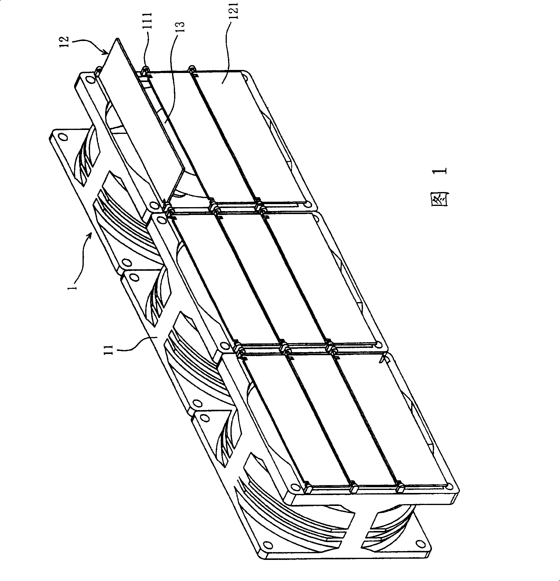
When a certain fan 1 of the fan module fails and stops running, the window blade 121 closes the sash structure 12 due to gravity or inertia, preventing the system from recharging the air volume due to back pressure, causing the failed fan 1 to reverse and causing the overall reduced cooling capacity
[0003] However, the lack of setting of the sash structure 12 of the fan 1 is that: the sash 11 needs to add or re-make the corresponding fixing part 111 to install the sash structure 12 to increase the cost, and the sash structure 12 protruding from the sash 11 also requires additional work. The installation space, and the opening and closing method of the fan window structure 12 is limited by the arrangement of the fan module in the system, otherwise the window blade 121 cannot close the fan window structure 12 through gravity or inertia, so the fan window structure 12 cannot be closed. Design and use to achieve the best utility

Method used


Image

  • Fan with fan window structure and fan frame thereof
  • Fan with fan window structure and fan frame thereof
  • Fan with fan window structure and fan frame thereof

Examples


Embodiment Construction

[0020] A fan with a fan window structure and its fan frame according to a preferred embodiment of the present invention will be described below with reference to related drawings, wherein the same components will be described with the same reference symbols.

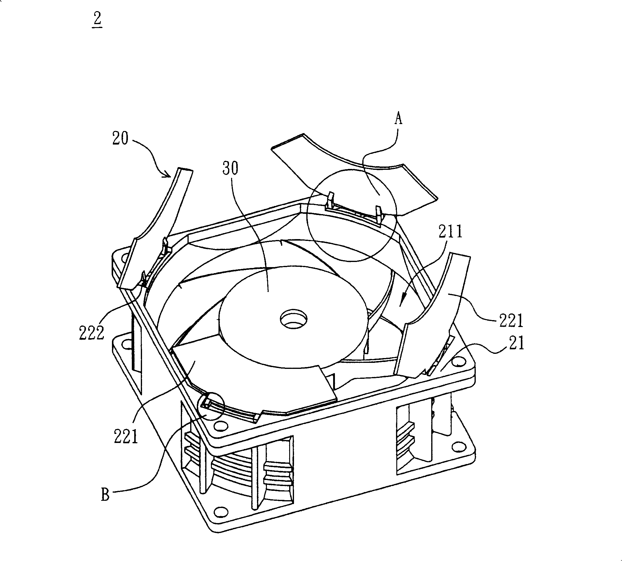
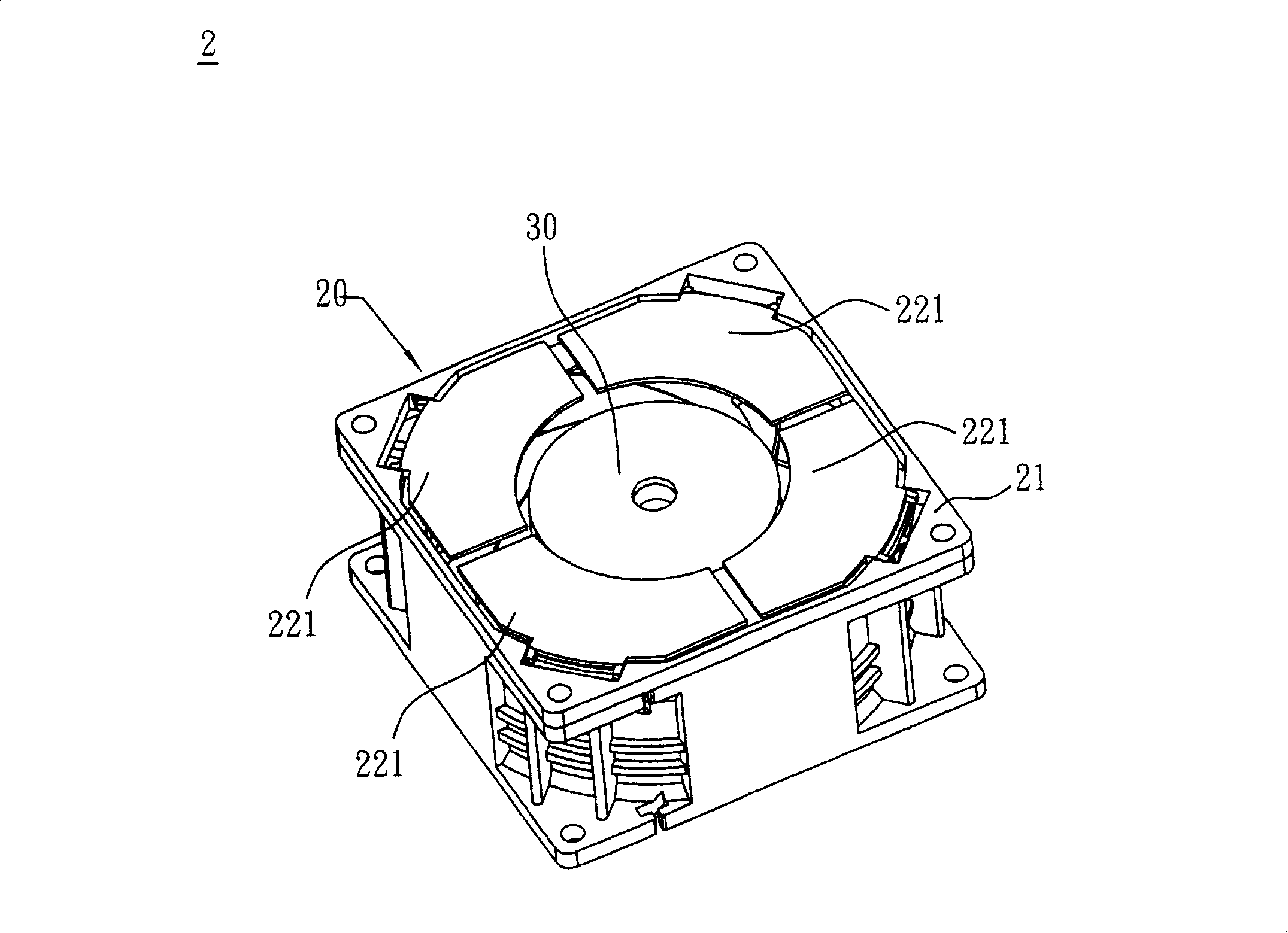
[0021] see figure 2 and Figure 4 , a fan 2 in a preferred embodiment of the present invention includes an impeller 30 , a motor (not shown in the figure) and a fan frame 20 . The fan 2 can be an axial flow fan or a centrifugal fan, and the motor is connected and drives the impeller 30 to rotate; the fan frame 20 accommodates the impeller 30 and the motor, and includes a frame body 21 and a window structure 22, wherein the fan window The structure 22 is connected to the air outlet side 211 of the frame body 21. The fan window structure 22 has a plurality of window blades 221 and a plurality of connecting parts 222. Each window blade 221 can be integrally formed with each connecting part 222, and the connecting parts 222...


PUM


Abstract

The invention discloses a fan, which is composed of an impeller, a motor and a fan frame. The motor is connected with and drives the impeller to rotate; the fan frame contains the impeller and the motor, as well as a frame body and a fan window structure which is connected with an air outlet side of the frame body and which is provided with a plurality of window leaf blades and a plurality of connecting pieces; and the connecting pieces respectively enable the window leaf blades to connect with corners of the frame body.

Description

technical field [0001] The invention relates to a fan and its fan frame, in particular to a fan with a fan window structure and its fan frame. Background technique [0002] At present, the computer system is becoming more and more complex, so the heat dissipation requirements of the fans are also increasing. If the fan fails and stops at the system end, the back pressure inside the system will cause the air volume to recharge, causing the failed fan to dissipate the air volume. , reducing the cooling capacity of the fan. Please refer to Fig. 1, the prior art uses louvers designed on the air outlet side of the fan frame to solve this problem, a kind of existing fan module includes a plurality of fans 1, each fan 1 includes a fan frame 11, a The impeller 13 and a motor (not shown). A window structure 12 is arranged on the air outlet side of each fan frame 11, and the fan window structure 12 has three window blades 121, and a fixing part 111 is added on the fan frame 11 to in...

Claims


Application Information

Patent Timeline
Patent Type & Authority Applications(China)
IPC IPC(8): F04D29/52F04D29/42F04D25/14
Inventor 李健铭陈英琦
Owner DELTA ELECTRONICS INC
Learn More