Field transportable high-power ultrasonic transducer assembly

a transducer and assembly technology, applied in the direction of cleaning process and apparatus, chemistry apparatus and process, cleaning using liquids, etc., can solve the problems of heat transfer, corrosion and/or crud on wetted surfaces, and/or degrade the performance of the associated system

Inactive Publication Date: 2006-05-25
ARGUELLES DAVID +2
View PDF13 Cites 15 Cited by
  • Summary
  • Abstract
  • Description
  • Claims
  • Application Information

AI Technical Summary

Benefits of technology

[0007] The present invention relates to an improved ultrasonic cleaning system incorporating one or more improvements including, for example, the use of permanently-attached flexible cables rather than conventional stainless steel flexible conduits normally attached to submersible transducers, the use of waterproof bulkhead connectors on the transducers in association with disconnectable flexible cable assemblies, the use of a submersible breakout assembly that allows multiple cables to be consolidated into a single flexible cable assembly, use of rigid cable guides and retainers that do not require separate fasteners for improved cables management in association with the breakout assemblies, and the use of an electronic switching unit whereby multiple ultrasonic transducers can be selectively driven by a single ultrasonic generator.

Problems solved by technology

A common problem experienced during operation of equipment having wetted surfaces, for example, boilers, chillers, heat exchangers and reactors, is the accumulation of corrosion and / or crud on the wetted surfaces.
These accumulations will tend to reduce flow rates, reduce heat transfer and / or degrade the performance of the associated system.
This condition results from the accumulation of deposits on the fuel assembly, particularly deposits incorporating boron on the upper portions of the fuel assembly, which result in undesirable local flux depressions.

Method used


Image

  • Field transportable high-power ultrasonic transducer assembly
  • Field transportable high-power ultrasonic transducer assembly
  • Field transportable high-power ultrasonic transducer assembly

Examples


Embodiment Construction

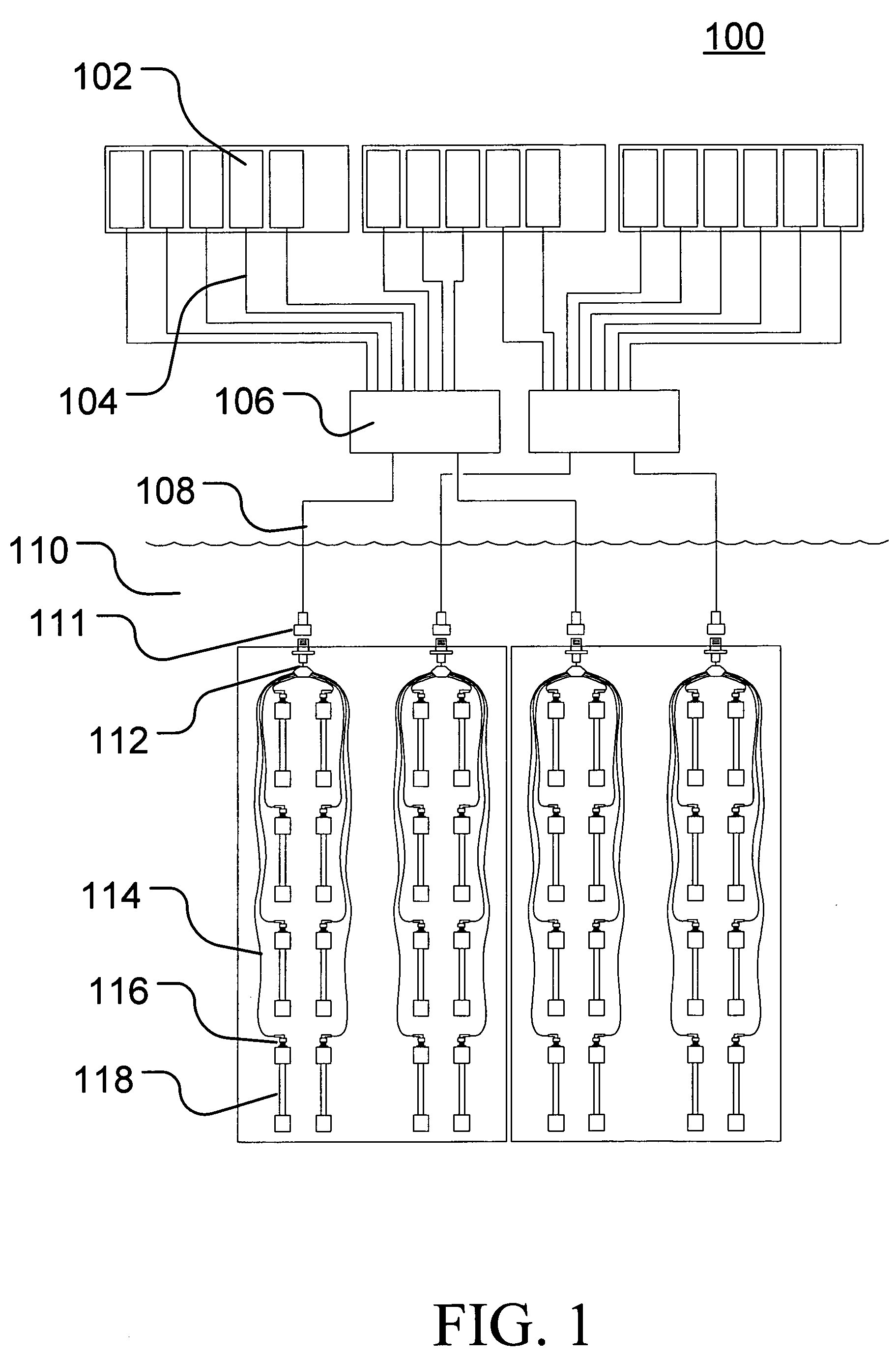
[0018] An exemplary embodiment of an ultrasonic cleaning system 100 according to the invention is illustrated in FIG. 1. As reflected in FIG. 1, a number of ultrasonic generators 102 may be connected through appropriate cables 104 and one or more optional switching units 106 to a number of ultrasonic transducers 118. By using this configuration with the incorporated switching units 106, each ultrasonic generator 102 may be used to provide or apply power to one or more ultrasonic transducers 118 in a predetermined, programmed and / or random sequence.

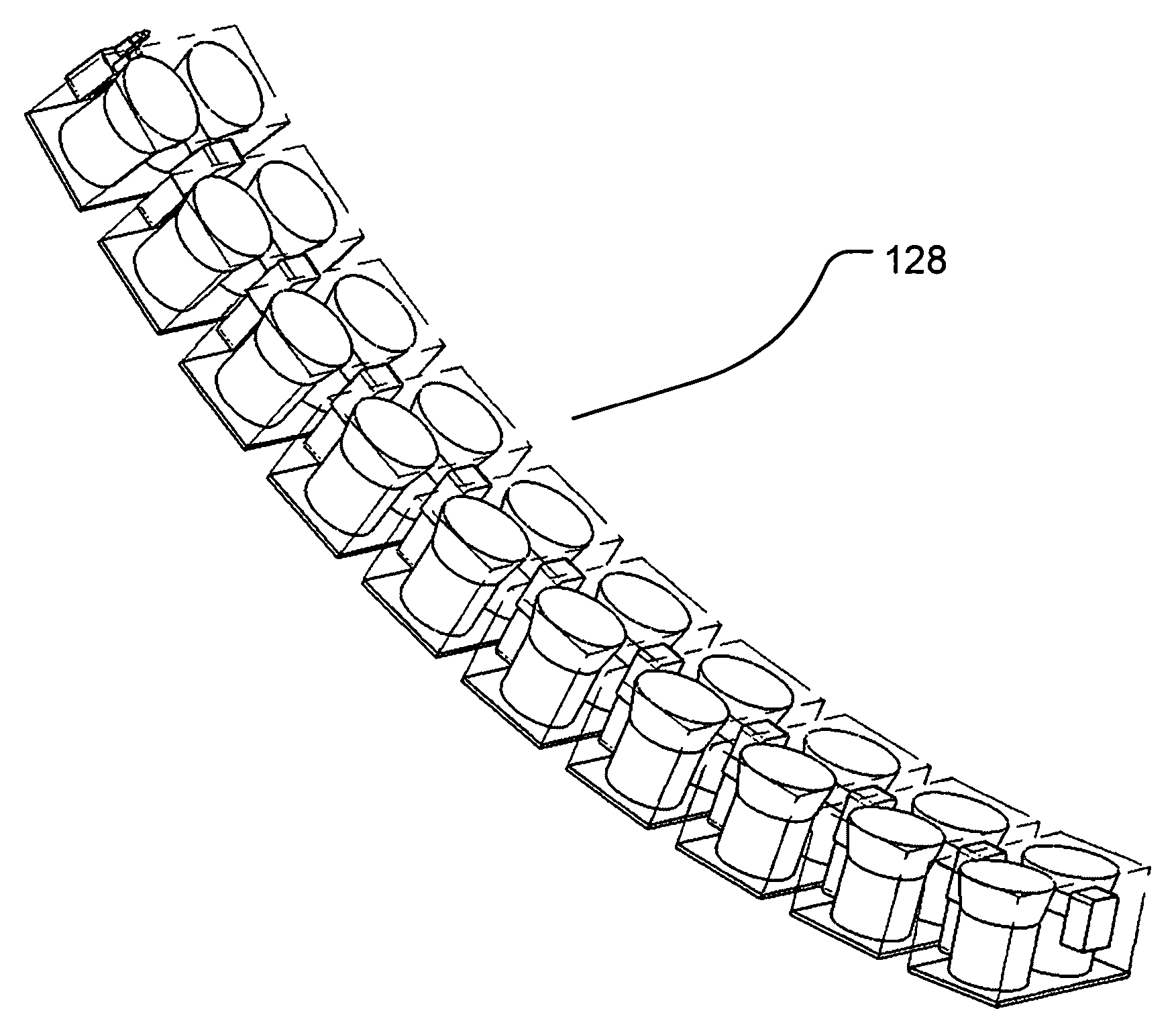
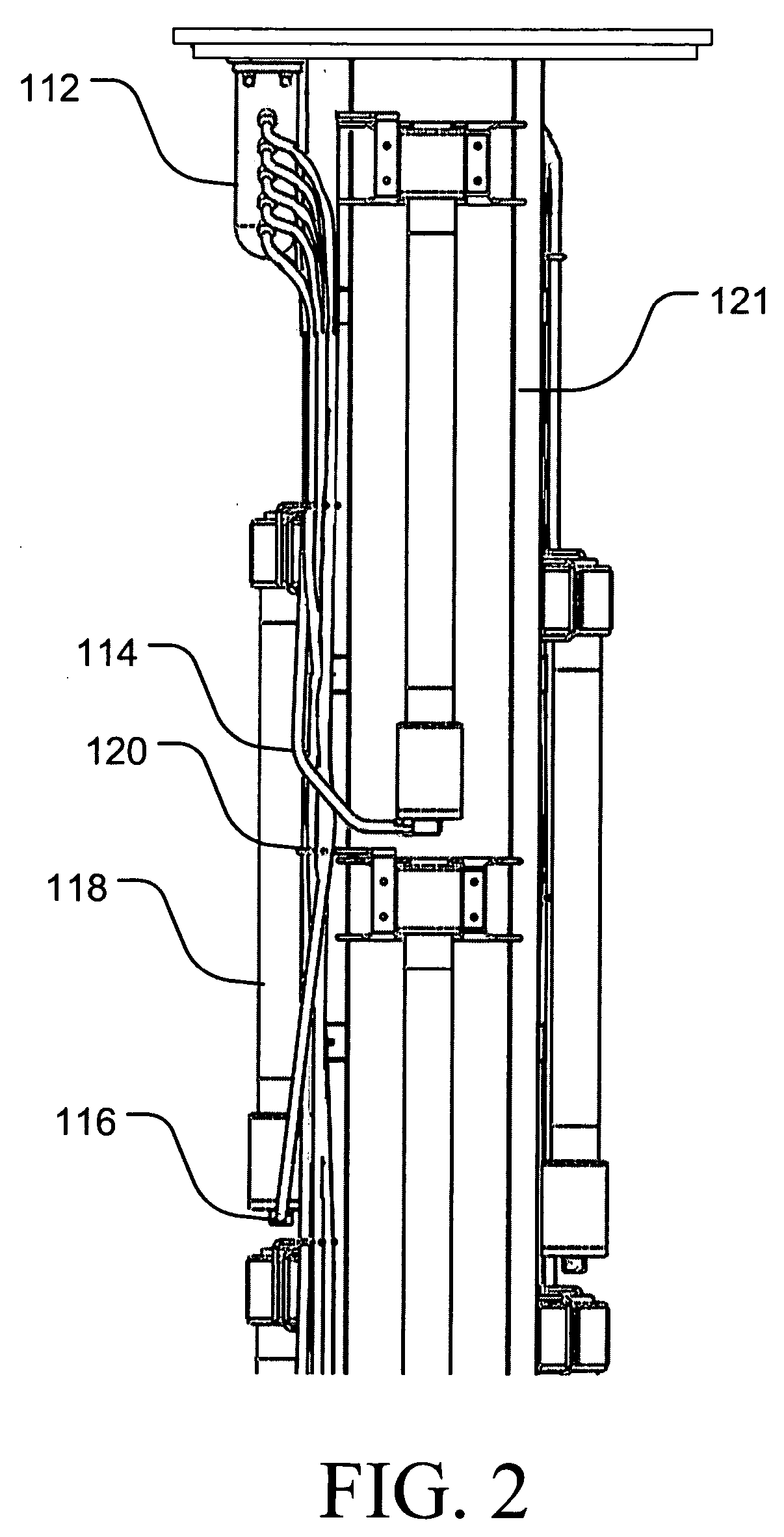
[0019] As illustrated in FIG. 1, the switching units 106 may be used to selectively alternate power from the generators 102 to a series of consolidated cable assemblies 108 that are associated with groups of transducers 118. Each of the cable assemblies 108 may, in turn, be connected to a breakout or distribution assembly 112 that distributes or separates these conductors into a corresponding series of cables 114, each cable typically bei...


PUM


Abstract

The present invention relates to an improved ultrasonic cleaning system incorporating one or more improvements including, for example, permanently-attached flexible cables, waterproof bulkhead connectors provided on the transducers, submersible breakout assemblies, rigid cable guides and retainers, and at least one electronic switching unit whereby multiple ultrasonic transducers can be selectively driven by a single ultrasonic generator. The improved ultrasonic cleaning system may be configured with various transducer arrangements including, for example, elongated transducers provided on a carrying frame or structure and a more planar array configuration that may be assembled from a plurality of transducer subassemblies.

Description

PRIORITY STATEMENT [0001] This U.S. non-provisional application claims benefit of priority under 35 U.S.C. § 119 from U.S. Provisional Patent Application No. 60 / 611,383, which was filed on Sep. 20, 2004, the entire contents of which are incorporated herein by reference.BACKGROUND OF THE INVENTION [0002] 1. Field of the Invention [0003] This invention relates to the control and configuration of cleaning systems incorporating ultrasonic transducers, particularly with regard to submersible transducer assemblies suitable for use in industrial applications, and more particularly, to improvements in cleaning systems incorporating ultrasonic transducers suitable for use in high-radiation fields such as found adjacent to irradiated nuclear fuel assemblies. [0004] 2. Background Art [0005] A common problem experienced during operation of equipment having wetted surfaces, for example, boilers, chillers, heat exchangers and reactors, is the accumulation of corrosion and / or crud on the wetted su...

Claims


Application Information

Patent Timeline
Patent Type & Authority Applications(United States)
IPC IPC(8): B08B3/10
CPCB08B3/12
Inventor ARGUELLES, DAVIDGROSS, DAVIDLUSZCZ, JOSHUA M.
Owner ARGUELLES DAVID
Why Eureka
Try Eureka