Electrostatic actuator

a technology of actuators and actuators, applied in piezoelectric/electrostrictive device details, printers, camera focusing arrangement, etc., can solve the problems of reducing affecting the accuracy of manufacturing, and limiting the battery that can be mounted in cameras, so as to reduce the variation in the movement speed

Inactive Publication Date: 2006-05-25
ALPS ALPINE CO LTD
View PDF8 Cites 4 Cited by
  • Summary
  • Abstract
  • Description
  • Claims
  • Application Information

AI Technical Summary

Benefits of technology

[0015] The present invention provides solutions to the problems described above, and it is an object of the present invention to provide an electrostatic actuator that can be downsized and generate large driving force.
[0017] It is another object of the present invention to provide an electrostatic actuator in which a relatively even movement speed can be achieved by reducing variation in the movement speed when an even movement speed is required.
[0030] Thus, the electrostatic actuator according to the present invention can be downsized and generate large driving force.
[0032] Moreover, in the electrostatic actuator according to the present invention, an even feed speed of the mover can be achieved, i.e., a relatively even movement speed can be achieved by reducing variation in the movement speed.

Problems solved by technology

However, in a case where an applied voltage is increased, there are limitations related to batteries that can be mounted in cameras, a withstandable voltage, and the like.
Moreover, in a case where the size of gaps between electrodes is decreased, there are limitations due to the accuracy of manufacturing.
However, the known electrostatic actuator described above has a structure in which the movement speed of the lens is not variable, and rough feed and fine feed of the lens cannot be alternately selected.
Thus, it is difficult to accurately stop the lens at the target position.
Moreover, when an accurate stop position of the lens is required, the lens needs to be moved back and forth several times. Thus, focusing operation requires a long time.
Moreover, a problem due to the structure exists, such that it is difficult to keep an even movement speed of the lens.

Method used


Image

  • Electrostatic actuator
  • Electrostatic actuator
  • Electrostatic actuator

Examples


first embodiment

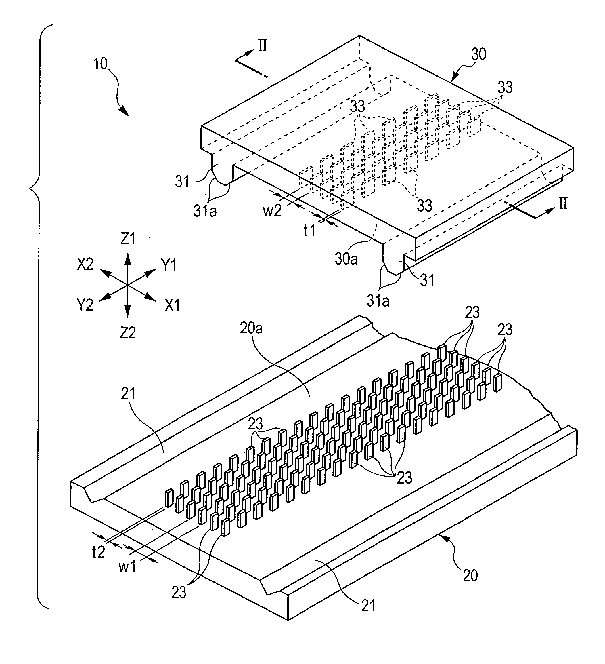
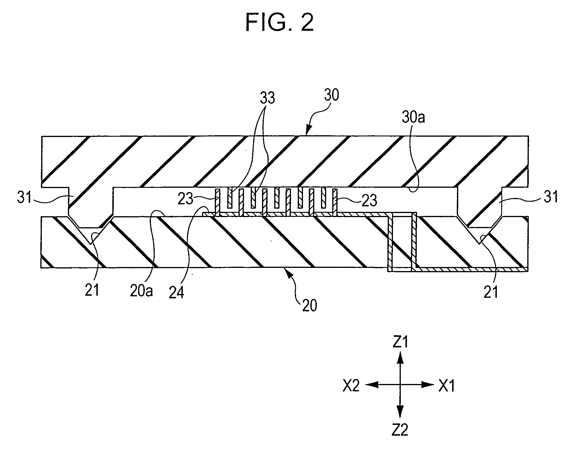
[0049]FIG. 1 is an exploded perspective view showing an electrostatic actuator according to the present invention. FIG. 2 is a sectional view taken along line II-II in FIG. 1 showing a state in which a stator and a mover oppose each other. FIG. 3 is a plan view partially showing the structure of the stator. FIG. 4 is a plan view showing relationships between electrodes on the stator side and electrodes on the mover side in the electrostatic actuator according to the present invention. Hereinafter, in the drawings, the Y direction indicates the movement direction, the X direction indicates the width direction, and the Z direction indicates the height direction.

[0050] As shown in FIG. 1, the electrostatic actuator 10 according to the present invention includes the stator 20 disposed at the Z2 side of the height direction shown in FIG. 1 and the mover 30 disposed at the Z1 side.

[0051] The stator 20 is a planar member that extends in the Y direction, which is the movement direction, an...

second embodiment

[0095] In the electrostatic actuator 10B, the length a1 of electrodes 33a, out of the electrodes 33 on the mover 30 side, which constitute a first group is the same as the length a2 of electrodes 33b, out of the electrodes 33 on the mover 30 side, which constitute a second group (a1=a2), as in the electrostatic actuator 10A. However, the electrostatic actuator 10B is different from the electrostatic actuator 10A in that the length b1 of gaps 34a that constitute the first group is smaller than the length b2 of gaps 34b that constitute the second group (b12) in the electrostatic actuator 10B. In the second embodiment, the difference between the lengths b1 and b2 is set to a value such that |b1−b2|=2·L1.

[0096] Accordingly, the total length T1 (=a1+b1) of the first group is smaller than the total length T2 (=a2+b2) of the second group. When the total length T1 of the first group is different from the total length T2 of the second group, as described above, i.e., when one group and anoth...

third embodiment

[0105] That is to say, the electrostatic actuator 10C shown as the third embodiment in FIG. 12 is a four-phase drive electrostatic actuator in which electrodes are disposed at uneven intervals.

[0106] As shown in FIG. 13, predetermined driving signals are applied to the electrodes 23, on the stator 20 side in the electrostatic actuator 10C according to the third embodiment, of A-phase to D-phase types.

[0107] When the mover 30 moves in the Y1 direction, in step ST1, voltages are applied to the A-phase electrodes and the B-phase electrodes. In step ST2, voltages are applied to the B-phase electrodes and the C-phase electrodes. In step ST3, voltages are applied to the C-phase electrodes and the D-phase electrodes. In step ST4, voltages are applied to the A-phase electrodes and the D-phase electrodes. When a cycle of these steps is repeated in order of ST1, ST2, ST3, and ST4, the mover 30 can be sequentially moved in the Y1 direction and put to states PO1, PO2, PO3, PO4, and PO1′, as sh...


PUM


Abstract

An electrostatic actuator includes a stator that includes a stator-side electrode group including a plurality of electrodes, a mover that includes a mover-side electrode group including a plurality of electrodes and that can move in a predetermined movement direction, this plurality of electrodes opposing the electrodes in the stator-side electrode group, a guide instrument that guides the mover, and a driving signal supply unit that generates driving signals and applies the driving signals between the stator-side electrode group and the mover-side electrode group. In one electrode group of these electrode groups, the electrodes and gaps have the same length and are alternately disposed in the movement direction, and the other electrode group includes a first group and a second group alternately disposed in the movement direction, each of the first and second groups including an electrode and a gap.

Description

BACKGROUND OF THE INVENTION [0001] 1. Field of the Invention [0002] The present invention relates to actuators that move lenses back and forth in, for example, cameras and cellular phones, and in particular, relates to an electrostatic actuator that uses electrostatic force (coulomb force). [0003] 2. Description of the Related Art [0004] A known electrostatic actuator is disclosed in, for example, Japanese Unexamined Patent Application Publication No. 2001-346385. FIG. 15 shows an overall structure of the electrostatic actuator shown in FIG. 1 in this document. FIG. 16 is a timing diagram showing driving signals that are applied to electrodes shown in FIG. 2 in this document. [0005] As shown in FIG. 15, this electrostatic actuator includes a first stator 2a and a second stator 2b that are disposed so as to oppose each other with a predetermined distance therebetween and includes a slidable mover 3 that is disposed between the first stator 2a and the second stator 2b. [0006] The firs...

Claims


Application Information

Patent Timeline
Patent Type & Authority Applications(United States)
IPC IPC(8): H02N1/00
CPCH02N1/004G02B7/09G03B13/36G03B3/10
Inventor FURUSHO, HIDETAKA
Owner ALPS ALPINE CO LTD
Why Eureka
Try Eureka