
Synchronizer, method of synchronizing signals and MIMO transceiver employing the same

a synchronizer and signal technology, applied in the field of communication systems, can solve the problems of phase noise becoming a multiple dimension problem, rf signals to add both constructively and destructively, and reduce the throughput data rate,

Inactive Publication Date: 2006-05-25
TEXAS INSTR INC
View PDF4 Cites 41 Cited by
  • Summary
  • Abstract
  • Description
  • Claims
  • Application Information

AI Technical Summary

Benefits of technology

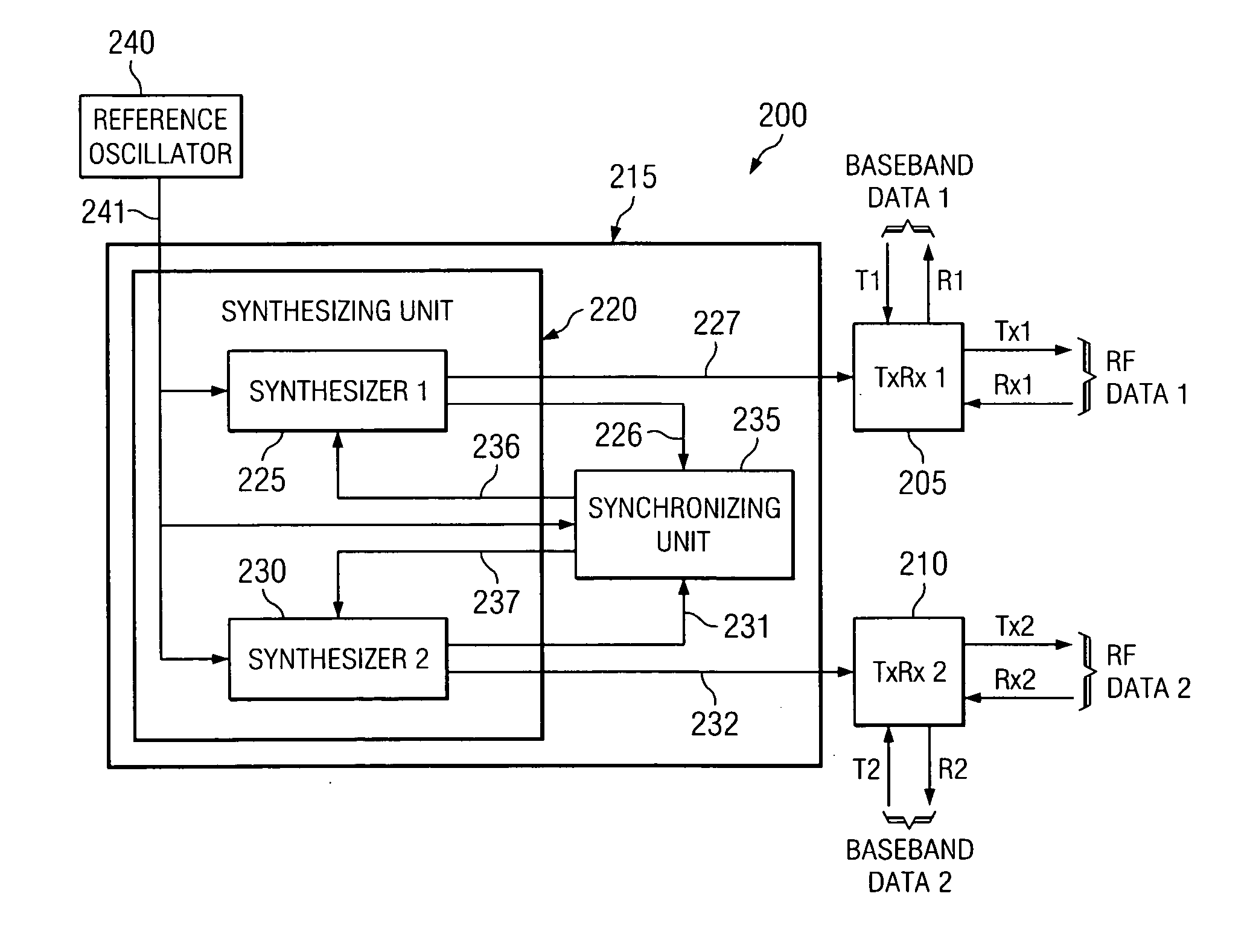
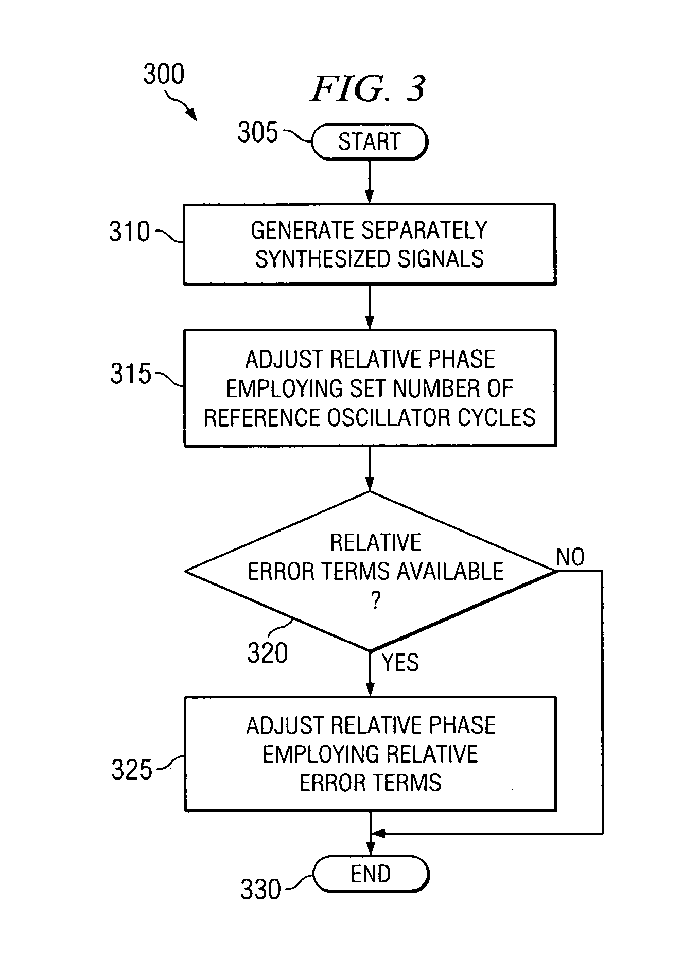
The present invention provides a synchronizer for use with a multiple-input, multiple-output (MIMO) transceiver employing multiple individual transceivers. The synchronizer generates separately synthesized radio frequency (RF) signals with relative phase differences and adjusts them to be less than a predetermined difference to provide synchronization of the multiple individual transceivers based on the predetermined difference. This allows for seamless communication among the multiple transceivers and reduces interference, improving the overall performance of the MIMO transceiver.

Problems solved by technology

However, when multiple transceivers are combined to form a MIMO transceiver, the phase noise becomes a multiple dimension problem.
Additionally, each synthesizer will have bounds for the phase noise that when combined with the different lock times will cause the RF signals to add both constructively and destructively depending on the relative phase of each synthesizer.
Therefore, relative phase behavior between various transmitters and receivers of the MIMO transceiver reduces the throughput data rate and lowers the overall general performance of the MIMO transceiver.

Method used


Image

  • Synchronizer, method of synchronizing signals and MIMO transceiver employing the same
  • Synchronizer, method of synchronizing signals and MIMO transceiver employing the same
  • Synchronizer, method of synchronizing signals and MIMO transceiver employing the same

Examples


Embodiment Construction

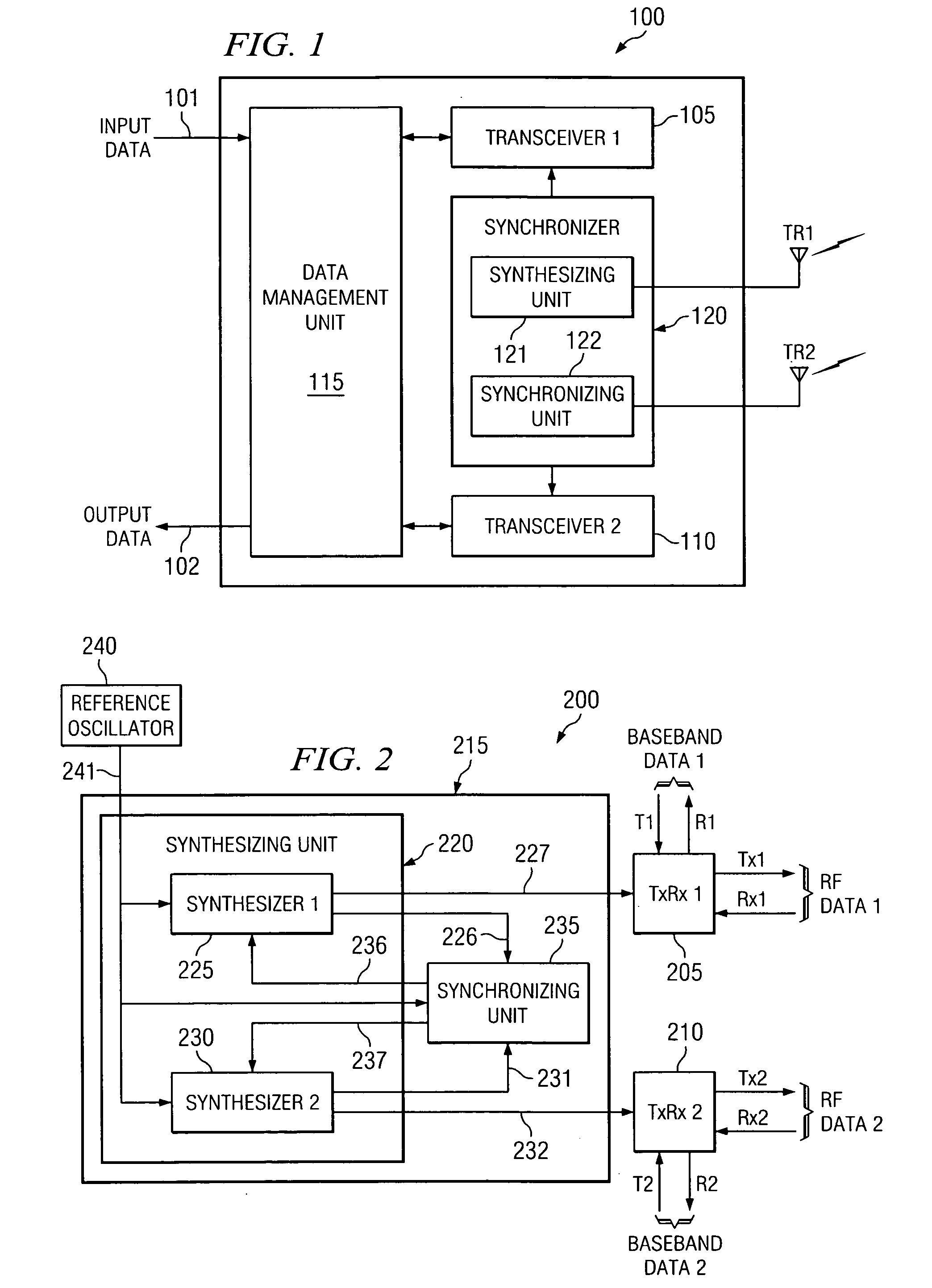
[0015] Referring initially to FIG. 1, illustrated is a diagram of an embodiment of a multiple-input, multiple-output (MIMO) transceiver, generally designated 100, constructed in accordance with the principles of the present invention. The MIMO transceiver 100 includes a first individual transceiver 105 coupled to a first antenna TR1 and a second individual transceiver 110 coupled to a second antenna TR2. The MIMO transceiver 100 also includes a data management unit 115 and a synchronizer 120, having a synthesizing unit 121 and a synchronizing unit 122, coupled to the first and second transceivers 105, 110. The data management unit 115 employs a data input 101 and a data output 102.

[0016] In the illustrated embodiment, each of the first and second individual transceivers 105, 110 contain first and second transmit systems and first and second receive systems, which are respectively coupled to the first and second antennas TR1, TR2. Each of these transmit and receive systems are emplo...


PUM


Abstract

The present invention provides a synchronizer for use with a multiple-input, multiple-output (MIMO) transceiver employing multiple individual transceivers. In one embodiment, the synchronizer includes a synthesizing unit coupled to a reference oscillator and configured to generate separately synthesized radio frequency (RF) signals having relative phase differences. Additionally, the synchronizer also includes a synchronizing unit coupled to the synthesizer unit and configured to adjust the relative phase differences of the separately synthesized RF signals to be less than a predetermined difference to provide synchronization of the multiple individual transceivers based on the predetermined difference.

Description

TECHNICAL FIELD OF THE INVENTION [0001] The present invention is directed, in general, to communication systems and, more specifically, to a synchronizer, a method of synchronizing signals and a MIMO transceiver employing the synchronizer or the method. BACKGROUND OF THE INVENTION [0002] Multiple-input, multiple-output (MIMO) communication systems transmit and receive different data symbols concurrently using multiple antennas. MIMO communication systems employ a coordinating collection of single-dimension transmitters to send a vector symbol of information. Correspondingly, a coordinating collection of single-dimension receivers are employed to receive one or more copies of such a transmitted vector of symbol information. MIMO communication systems may employ a MIMO transmitter at one end of a communication path, and a MIMO receiver at the other end if only one-way communication is required. More typically, a MIMO transceiver is employed at each end to allow transmission and recept...

Claims


Application Information

Patent Timeline
Patent Type & Authority Applications(United States)
IPC IPC(8): H04L1/02
CPCH03J2200/02H04B7/04H04L1/06H04L2027/003H04L2027/0065
Inventor MAGEE, DAVID P.DIRENZO, MICHAEL T.
Owner TEXAS INSTR INC
Learn More