
Systems and methods for improved biometric feature definition

a biometric and feature technology, applied in the field of biometrics, can solve problems such as skin distortion, changes in image contrast, other artifacts, and introduction of artifacts, and achieve the effect of reducing the ability to properly determine matching fingerprint images

Active Publication Date: 2006-05-25
HID GLOBAL CORP
View PDF99 Cites 103 Cited by
  • Summary
  • Abstract
  • Description
  • Claims
  • Application Information

AI Technical Summary

Problems solved by technology

Differences in orientation and pressure of the finger cause distortions of the skin, changes in image contrast, and other artifacts that affect the characteristics of the fingerprint image.
The sensor itself may also introduce artifacts into the image that vary from image to image.
These sensor artifacts may include fixed-pattern noise that varies in some manner across the image plane and a variety of high-frequency image noise sources, including shot noise and dark noise among other types of noise sources.
Generally, fewer biometric features can be extracted from this reduced image area, resulting in a degraded ability to properly determine matching fingerprint images.
But the ability to determine the presence of a true biometric feature is still compromised by the differences in finger orientation, translation, rotation, distortion, and other image artifacts across the set of enrollment images.
In addition, the ability to collect and compare multiple fingerprint images is usually only viable during the enrollment procedure.
In such scenarios, there is no opportunity to enhance the feature detection of a test sample by using multiple images.
But these external characteristics are subject to wear, contamination, or changes that result from differences in environmental conditions, all of which may further compromise the definition of fingerprint features.
Thus, the reliance of conventional fingerprint sensors on measuring only the surface characteristics of the finger has a number of negative consequences.
First, the number and quality of biometric features that may be detected is limited to those features present on the surface skin, which may be worn or missing.
Second, a sensor that relies exclusively on features present on the external surface skin is susceptible to a security breach using an artificial replica of an authorized fingerprint pattern.
This procedure is time consuming, awkward for the user, and generally requires a skilled operator to assist the proper collection of such data.
Consequently, this method of fingerprint image collection is not generally used by automated and unattended biometric sensors, even though the greater image area could in principle provide improved performance.

Method used


Image

  • Systems and methods for improved biometric feature definition
  • Systems and methods for improved biometric feature definition
  • Systems and methods for improved biometric feature definition

Examples


Embodiment Construction

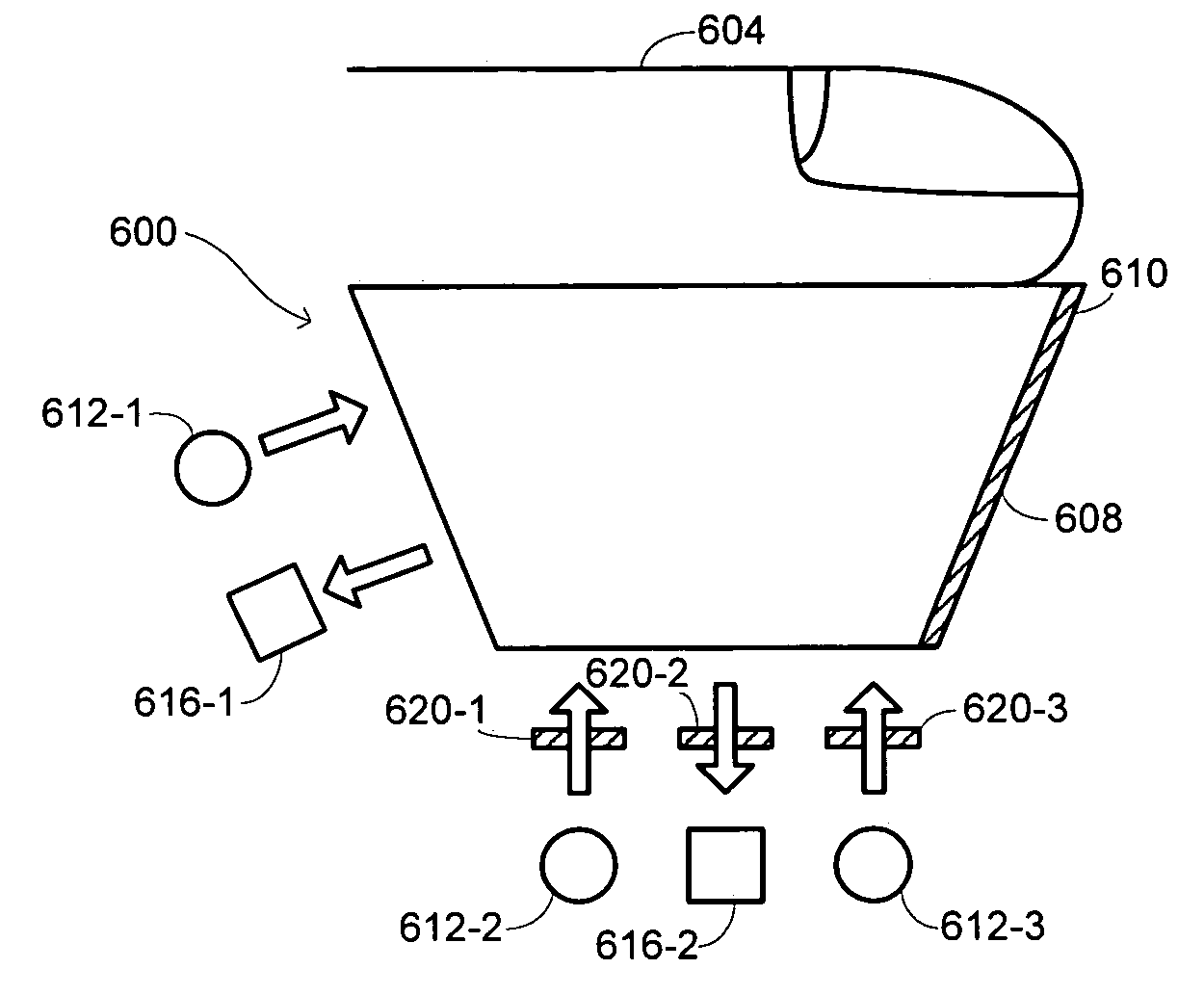
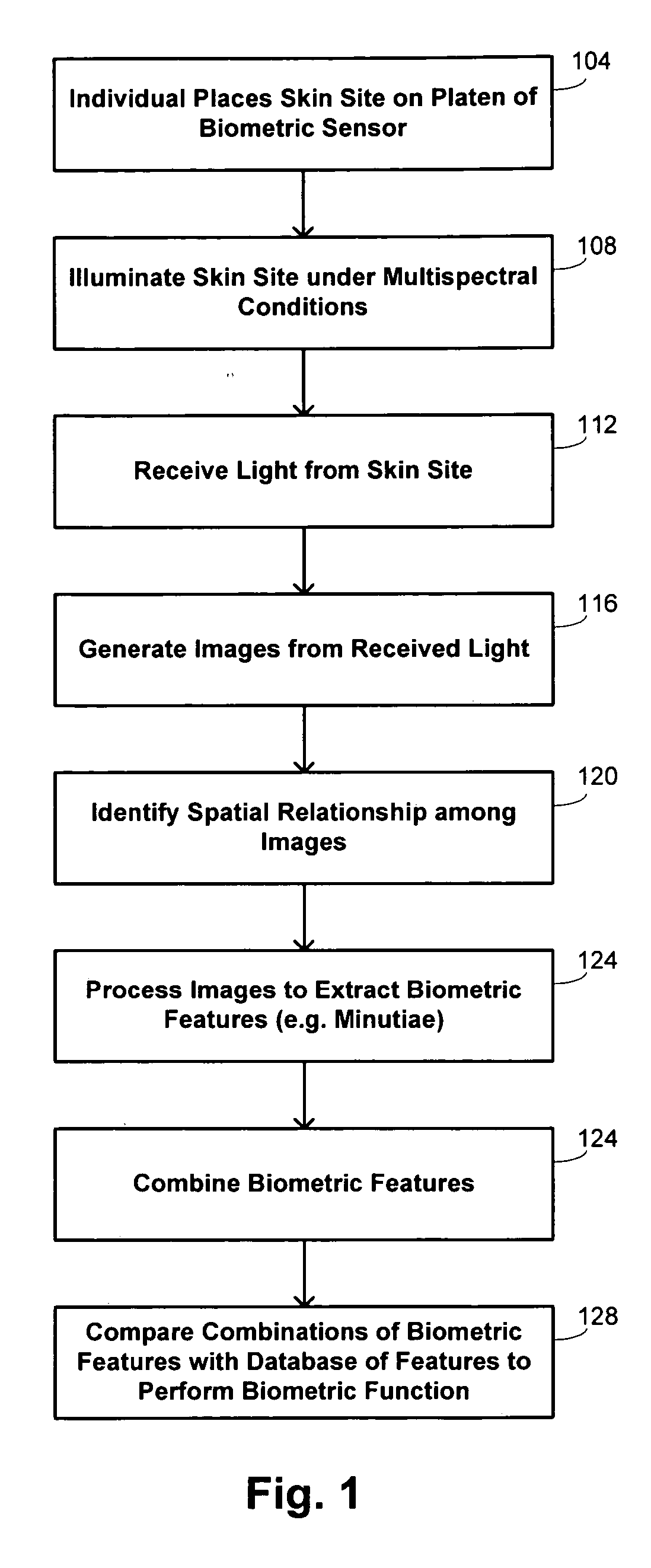
[0031] Embodiments of the invention provide systems and methods for performing a biometric function that make use of the acquisition of multiple images of a skin site taken under different optical conditions during a single illumination session. The images thus contain different information about the skin site that may be combined in various manners to produce reliable definitions of biometric features. Use of a single illumination session permits the images to be generated for a substantially fixed position of the skin site, removing uncertainties in the relative orientation of features between images and resulting in increased accuracy and reduced processing requirements.

[0032] The term “biometrics” refers generally to the statistical analysis of characteristics of living bodies. One category of biometrics includes “biometric identification,” which commonly operates under one of two modes to provide automatic identification of people or to verify purported identities of people. A...


PUM


Abstract

Methods and systems are provided for performing a biometric function. A purported skin site of an individual is illuminated under distinct optical conditions during a single illumination session for a fixed position of the purported skin site. Light from the purported skin site is received for each of the optical conditions. Images of the purported skin site are generated from the received light. The images are analyzed to identify a biometric feature as a characteristic in a portion of at least one of the images. The biometric function is implemented in accordance with an identification of the biometric feature.

Description

CROSS-REFERENCES TO RELATED APPLICATIONS [0001] This application is a nonprovisional of, and claims the benefit of the filing date of, U.S. Prov. Pat. Appl. No. 60 / 641,991, entitled “SYSTEMS AND METHODS FOR IMPROVED BIOMETRIC FEATURE DEFINITION,” filed Jan. 7, 2005, by Robert K. Rowe. [0002] This application is a continuation-in-part of U.S. patent application Ser. No. 10 / 818,698, entitled “MULTISPECTRAL BIOMETRIC SENSOR,” filed Apr. 5, 2004, by Robert K. Row. et al., which is a nonprovisional of each of U.S. Prov. Pat. Appl. No. 60 / 460,247, filed Apr. 4, 2003, U.S. Prov. Pat. Appl. No. 60 / 483,281, filed Jun. 27, 2003, U.S. Prov. Pat. Appl. No. 60 / 504,594, filed Sep. 18, 2003, and U.S. Prov. Pat. Appl. No. 60 / 552,662, filed Mar. 10, 2004. [0003] This application is also a continuation-in-part of U.S. patent application Ser. No. 11 / 115,100, entitled “MULTISPECTRAL IMAGING BIOMETRICS,” filed Apr. 25, 2005, by Robert K. Rowe, which is a nonprovisional of each of U.S. Prov. Pat. Appl. N...

Claims


Application Information

Patent Timeline
Patent Type & Authority Applications(United States)
IPC IPC(8): G06K9/00G06V40/40
CPCG06K9/00013G06K9/00046G06K9/0012G06K9/00899A61B5/443G06V40/1324G06V40/1394G06V40/40A61B5/117G06V10/40G06F18/00
Inventor ROWE
Owner HID GLOBAL CORP
Learn More