
Construction system

Inactive Publication Date: 2006-06-01
TIMBERFIX
View PDF10 Cites 26 Cited by
  • Summary
  • Abstract
  • Description
  • Claims
  • Application Information

AI Technical Summary

Benefits of technology

[0006] Both end profiles of the first and second coupling parts may have an aperture, with the apertures being registrable so both may be slidingly engaged by the locking pin when rigidly coupling the beam to the post. One end profile may include a pair of apertures configured to register with opposite sides of the aperture in the other end profile when rigidly coupling the beam to the post. In this way, the pair of apertured portions of the one end profile define a recess for receiving the apertured portion of the other end profile. The pair of apertured portions thus act as “stops”, preventing unwanted movement of the beam relative to the post along the axis of the locking pin when registered in the apertures.
[0024] Alternatively, the body may comprise a rod extending the entire length of the brace, thereby forming a reinforced brace. The rod may be parallel to, but radially offset from, the longitudinal axis of the brace. The rod may be metallic and may itself be configured to support the intended load. The reinforced brace may thereby continue to function as a brace despite extensive fire damage to wooden parts, thereby offering improved fire-rating in comparison to conventional wooden braces.

Problems solved by technology

However, a large number of different components are seemingly required to complete even one building, and alternative components need to be provided if a full range of different types of buildings are to be offered.

Method used


Image

  • Construction system
  • Construction system
  • Construction system

Examples


Embodiment Construction

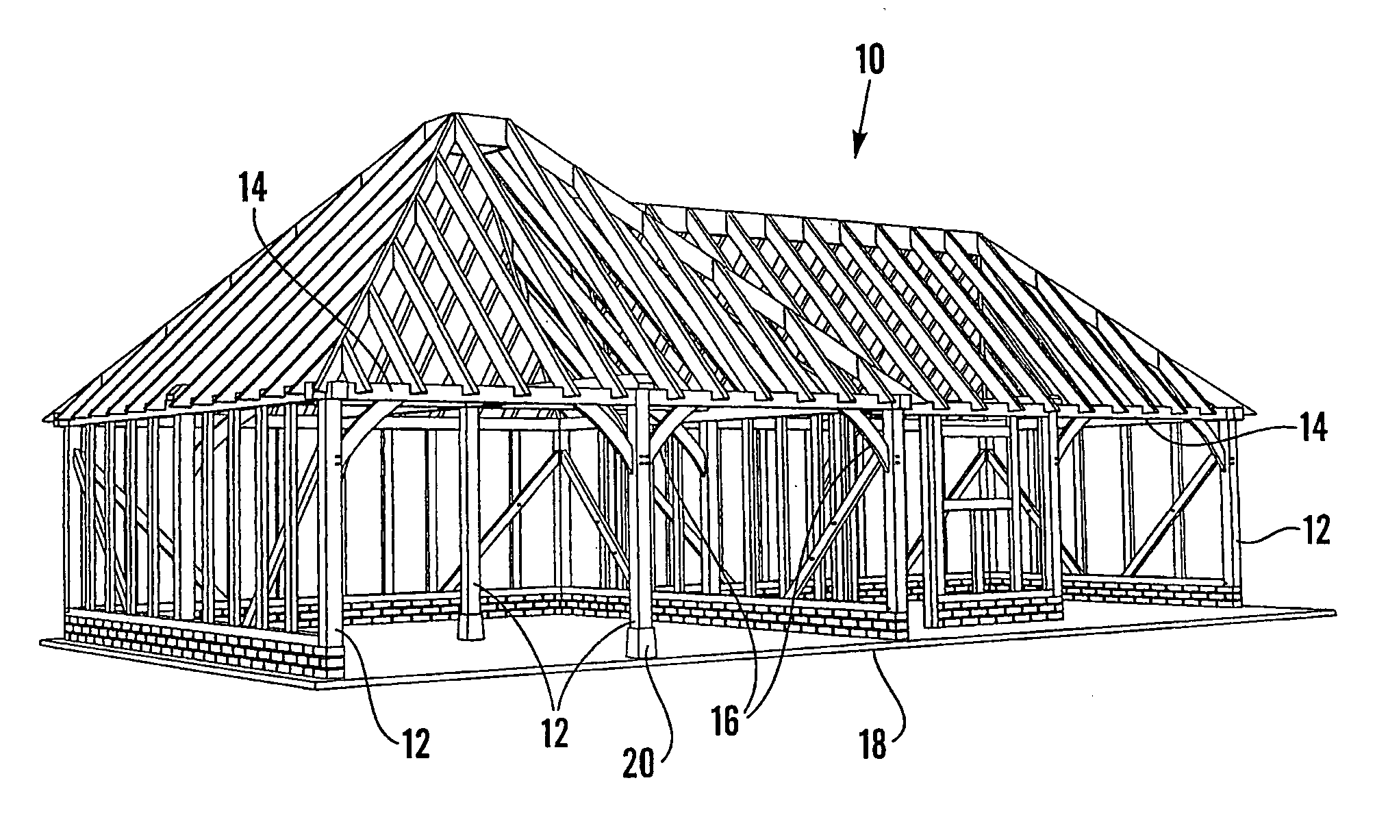
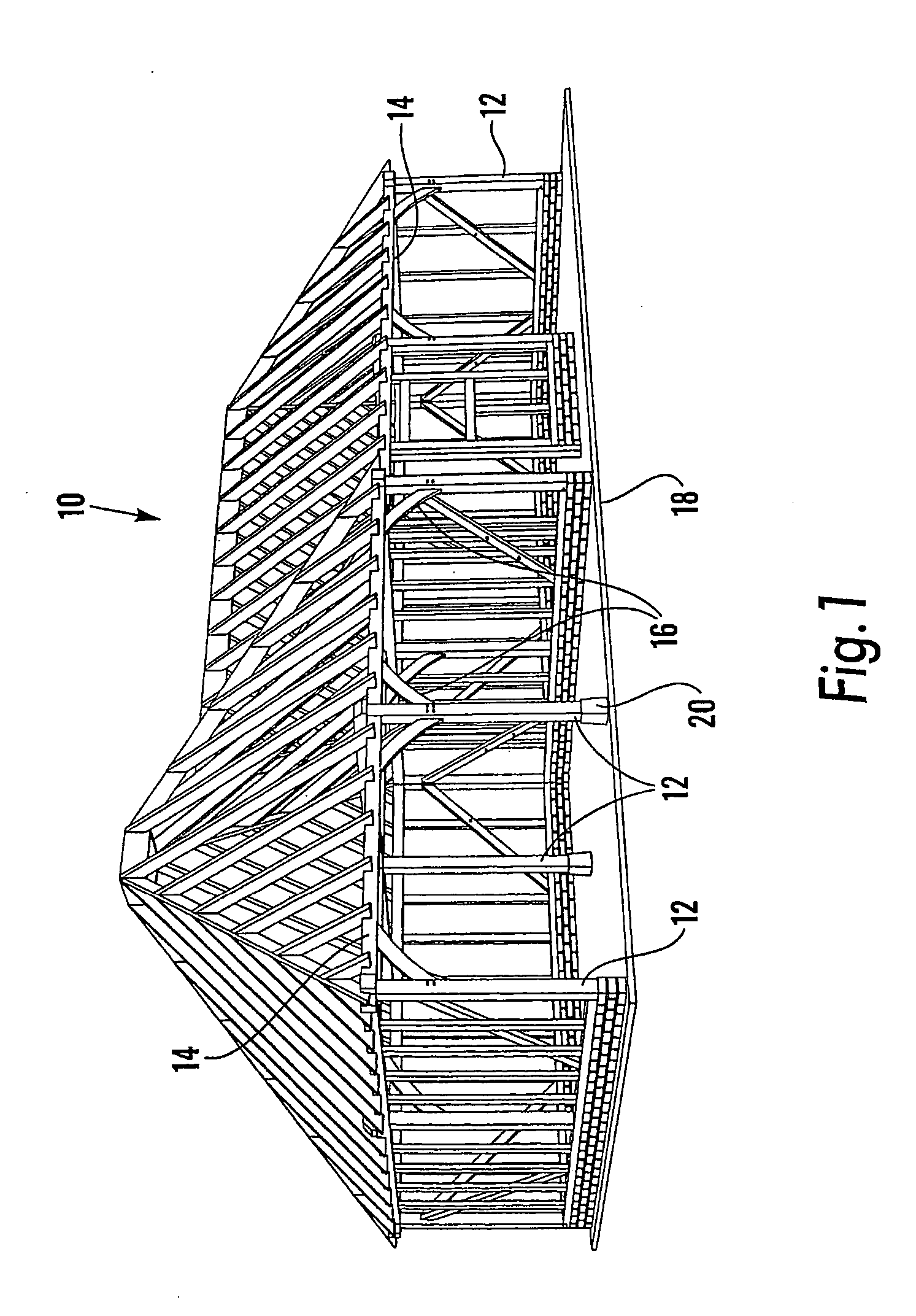
[0047]FIG. 1 shows the superstructure of a timber-framed building (10) which comprises a plurality of vertical posts (12) supporting horizontal beams (14). Braces (16) are fitted between beams (14) and posts (12) to increase stiffness and lend architectural interest. The posts (12) are fixed to the ground (18), in some cases using base plates (20) which are bolted to the foundations. The posts (12) and beams (14) are coupled together by coupling parts (30,50) connected by locking pins (70) concealed from view by the posts and beams themselves.

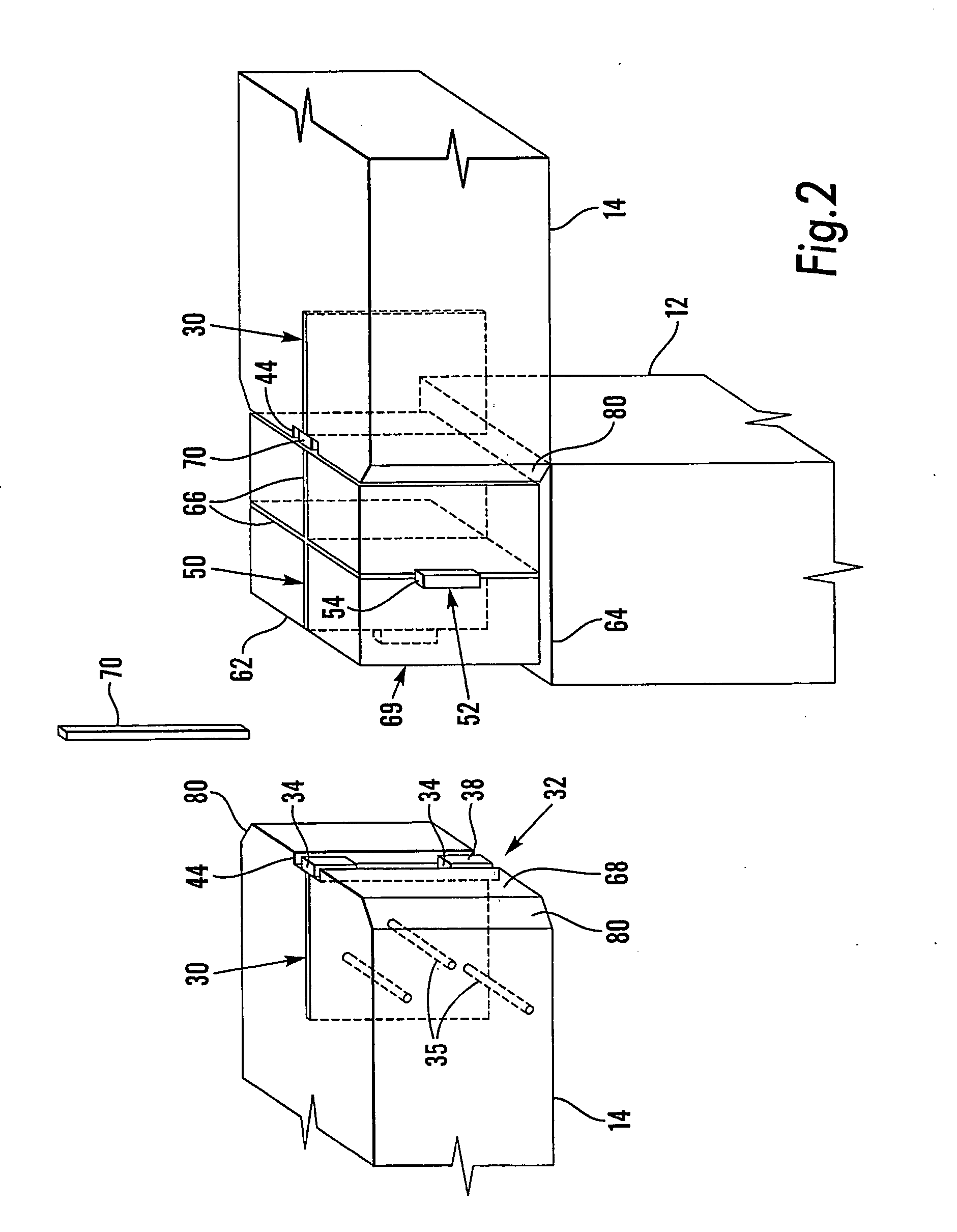
[0048]FIG. 2 shows in detail how a beam (14) is coupled to a post (12) in accordance with the present invention. A first coupling part (30) is attached to one end of a beam (14), and a second coupling part (50) is attached to the post (12). The coupling parts (30,50) have end profiles (32,52) with apertures (34,54) which are registrable. Once registered, the apertures are slidably engaged by a locking pin (70), coupling the beam to the post. T...


PUM


Abstract

A kit of components for constructing a building comprises a first coupling part (30) embedded in one end of a beam (14), and a second coupling part (50) embedded in one end of a post (12). The coupling parts (30,50) have end profiles (32,52) with apertures (34,54) which are registrable when the beam (14) abuts the post (12). Once registered with beam (14) resting on ledge (64) the apertures are slidably engaged by a locking pin (70), coupling the beam (14) to the post (12).

Description

TECHNICAL FIELD [0001] The present invention relates to a system for constructing a building, particularly but not exclusively timber-framed constructions. BACKGROUND ART [0002] There is considerable interest in traditional-looking timber-framed buildings, for use as garages, or more complex garden outbuildings, or even as extensions to existing houses. In recent time, a modular system of construction has been adopted for buildings of this kind in order to introduce cost savings associated with a manufactured item as opposed to a bespoke one. In the modular system the framework components are standardized to a degree so that they may be put together in different permutations to provide a variety of different building designs. However, a large number of different components are seemingly required to complete even one building, and alternative components need to be provided if a full range of different types of buildings are to be offered. [0003] The present applicant has appreciated ...

Claims


Application Information

Patent Timeline
IPC IPC(8): E04C3/02E04B1/26
CPCE04B1/2604E04B2001/2696
Inventor ABBOT-WILCOX, PHILIPPE ANDRE
Owner TIMBERFIX
Learn More