Cutting machine

a cutting machine and cutting blade technology, applied in the field of cutting machines, can solve the problems of inability to precisely cut the workpiece along a predetermined dividing line, long distance between the cutting means and the cutting means, and scattered cutting water, etc., and achieve the effect of easy exchange of cutting blades

Active Publication Date: 2006-06-01
DISCO CORP
View PDF5 Cites 45 Cited by
  • Summary
  • Abstract
  • Description
  • Claims
  • Application Information

AI Technical Summary

Benefits of technology

[0014] Since in the cutting machine according to the present invention, the spindle unit is mounted on the cutting-in feed base provided on the other flank of the gate-like support frame, on the alignment means side through the opening, the alignment means and the cutting means are located at positions close to each other, whereby alignment information is reflected on the cutting means without causing a mechanical error. Further, since the alignment means and the cutting blades are located at positions close to each other, they are at a close distance from the operator who is located on the operation side of the machine housing, thereby making it easy to exchange the cutting blades.

Problems solved by technology

Since in the above-described cutting machine, the cutting means and the alignment means are arranged on the sides opposite to each other, of the interposed gate-like support frame, the distance between the alignment means and the cutting means becomes long, thereby causing the following problem.
That is, when the distance between the alignment means and the cutting means is long, there is a probability that a case where alignment information obtained by the alignment means is not reflected on the cutting means properly by a mechanical error, thereby making it impossible to cut the workpiece along a predetermined dividing line precisely.
Further, since the cutting means cuts the workpiece while cutting water is supplied, the cutting water is scattered.
When the cutting means is installed at a long distance from the alignment means, it is difficult to exchange or adjust the cutting blade.

Method used


Image

  • Cutting machine
  • Cutting machine
  • Cutting machine

Examples


Embodiment Construction

[0019] A preferred embodiment of the cutting machine constituted according to the present invention will be described in detail herein under with reference to the accompanying drawings.

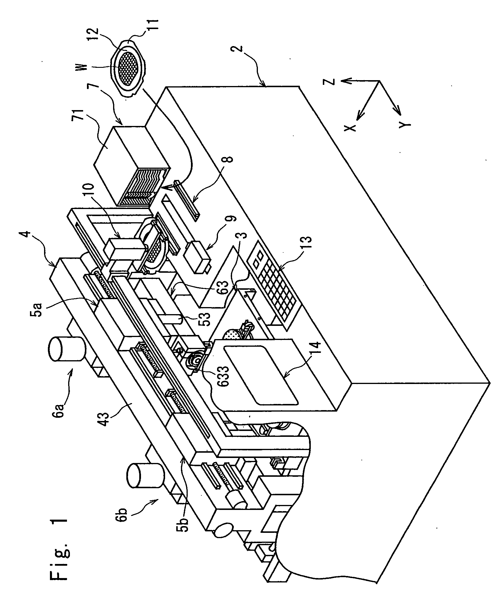
[0020]FIG. 1 is a perspective view, partly broken away, of a cutting machine constituted according to the present invention.

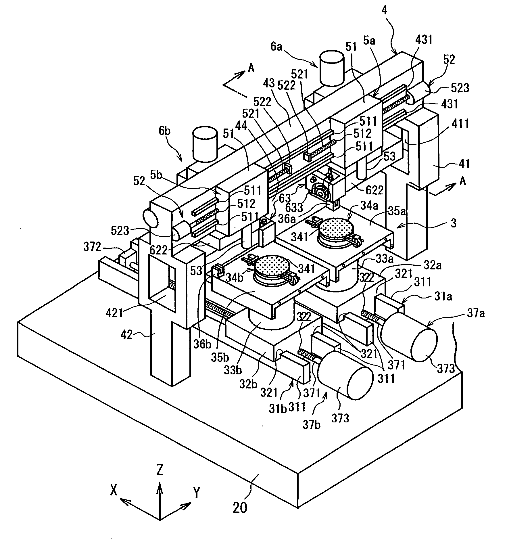
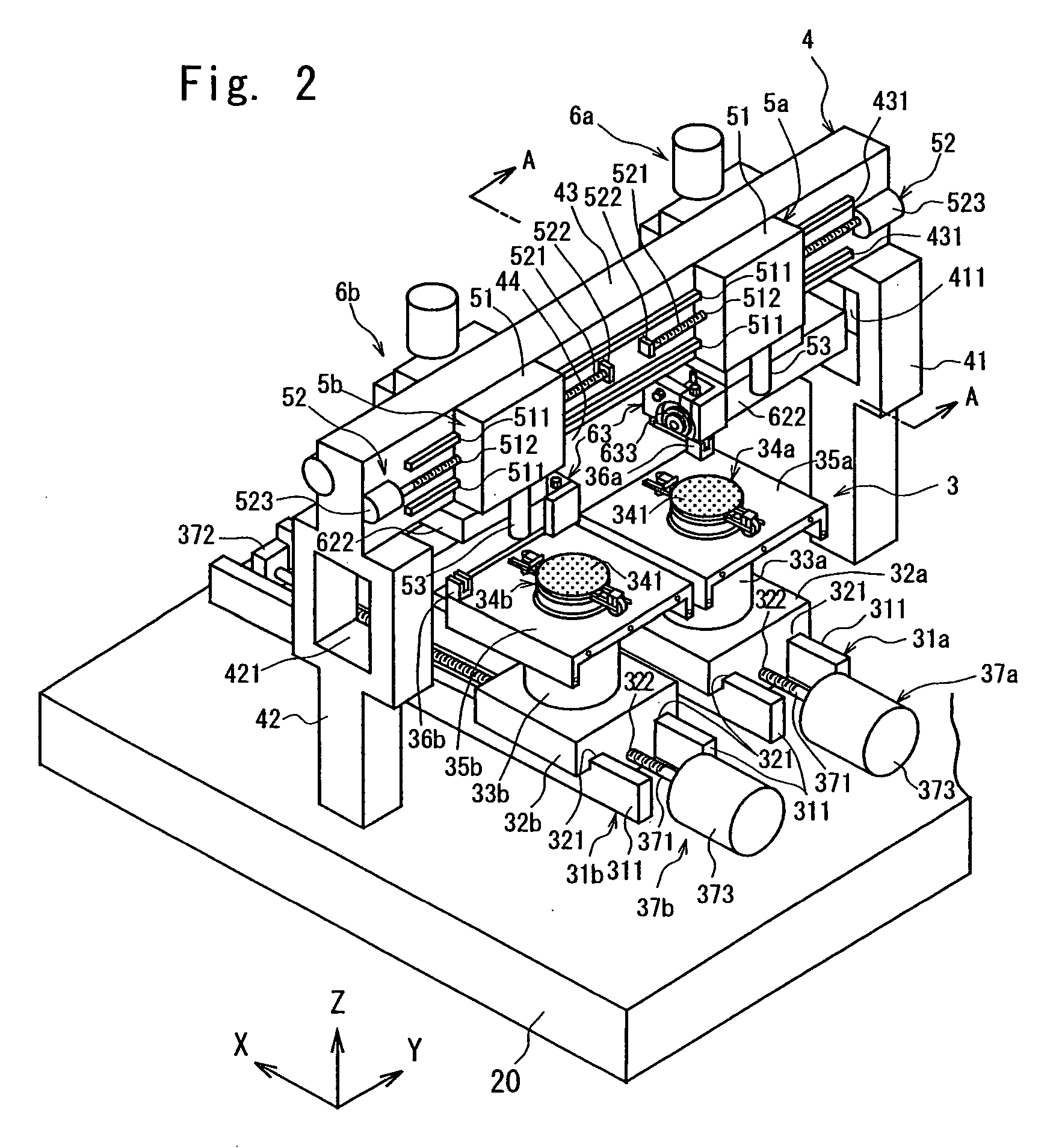
[0021] The cutting machine shown in FIG. 1 has a substantially rectangular parallelepiped housing 2. In this housing 2, there is arranged a chuck table mechanism 3 that holds a workpiece such as semiconductor wafer and moves it in a cutting-feed direction indicated by an arrow X. This chuck table mechanism 3 will be described with reference to FIG. 2.

[0022] The above chuck table mechanism 3 in the illustrated embodiment comprises a first guide rail 31a and a second guide rail 31b on the top surface of a base 20 installed in the above housing 2. The first guide rail 31a and the second guide rail 31b each consist of a pair of rail members 311 and 311, which extend in parallel to...


PUM

PropertyMeasurementUnit
areaaaaaaaaaaa
distanceaaaaaaaaaa
mechanical erroraaaaaaaaaa

Abstract

A cutting machine comprising a chuck table for holding a workpiece, which is arranged such that it can move along a guide rail extending in a predetermined direction, a gate-like support frame that is arranged straddling the guide rail and has an opening for allowing the movement of the chuck table, an alignment means arranged on one flank of the gate-like support frame, and a cutting means arranged on the other flank of the gate-like support frame, wherein the cutting means is composed of an indexing-feed base arranged on the other flank of the gate-like support frame such that it can move in a direction perpendicular to the guide rail, a cutting-in feed base arranged on the indexing-feed base such that it can move in a direction perpendicular to the holding surface of the chuck table, and a spindle unit that is mounted on the cutting-in feed base and has a cutting blade, the spindle unit being arranged on the alignment means side through the opening of the gate-like support frame.

Description

FIELD OF THE INVENTION [0001] The present invention relates to a cutting machine for cutting a workpiece such as a semiconductor wafer or the like. DESCRIPTION OF THE PRIOR ART [0002] In the production process of a semiconductor device, for example, individual semiconductor chips are manufactured by forming a circuit such as IC or LSI in a large number of areas sectioned by dividing lines called “streets” formed in a lattice pattern on the front surface of a substantially disk-like semiconductor wafer, and dividing the semiconductor wafer into the areas having a circuit formed thereon along the dividing lines. A cutting machine is generally used as a dicing machine to divide the semiconductor wafer. This cutting machine comprises a chuck table for holding a workpiece and a cutting means having a cutting blade for cutting the workpiece held on the chuck table, and cuts the workpiece by moving the chuck table relative to the cutting means while the cutting blade is rotated. [0003] The...

Claims


Application Information

Patent Timeline
Patent Type & Authority Applications(United States)
IPC IPC(8): B26D1/56
CPCB28D5/023B28D5/024B28D5/029Y10T83/4734B26D3/00B26D7/01
Inventor FUJINAMI, KOICHI
Owner DISCO CORP
Why Eureka
Try Eureka