Identification method for touch control device

a technology of capacitive touch control and identification method, which is applied in the direction of electronic switching, pulse technique, instruments, etc., can solve the problems of difficult to solve troublesome problems, sensitivity and sensing capability of touch control device seriously affected, and the inability to improve sensitivity and sensing area of touch control devi

Inactive Publication Date: 2006-06-01
HOLTEK SEMICON
View PDF2 Cites 46 Cited by
  • Summary
  • Abstract
  • Description
  • Claims
  • Application Information

AI Technical Summary

Benefits of technology

[0019] Preferably, the step (b) further includes: (b1) eliminating the first energy stored in the integrator.

Problems solved by technology

However, if a touch control device with the need of having a large amount of keys / pad positions uses the above-mentioned identification method for determining whether or which key / pad position is touched, the sensitivity and the sensing capability of the touch control device would be seriously affected, since an error resulting from plural coupling capacitors or the equivalent capacitor thereof is generated.
That is to say, the conventional identification method is suitable for a capacitive touch control device with a small amount of keys / pad positions, however while it is applied for the capacitive touch control device with a large amount of keys / pad positions, the sensitivity and the sensing area thereof are unable to be improved, since the energy stored in the equivalent capacitance for each key / pad position is not uniform distributed.
Nevertheless, now the following two troublesome problems are still hard to be solved.
Firstly, although the capacitance of each capacitor is labeled identically, actually it is different from each other due to the producing inaccuracy in the fabrication.
However it is a time consuming and laboring process.
Second, since the thickness of the copper foil or the circuit board in the wash processing for capacitance preparation is not uniform, the equivalent capacitance for the pad will be different.
However it is also a time consuming and laboring process.
In conclusion, even few variations are existed between the capacitors or the equivalent capacitance, it is still difficult to identify whether the key is in a touch or in a no-touch condition.

Method used


Image

  • Identification method for touch control device
  • Identification method for touch control device
  • Identification method for touch control device

Examples


Embodiment Construction

[0036] The present invention will now be described more specifically with reference to the following embodiments. It is to be noted that the following descriptions of preferred embodiments of this invention are presented herein for purpose of illustration and description only; it is not intended to be exhaustive or to be limited to the precise form disclosed.

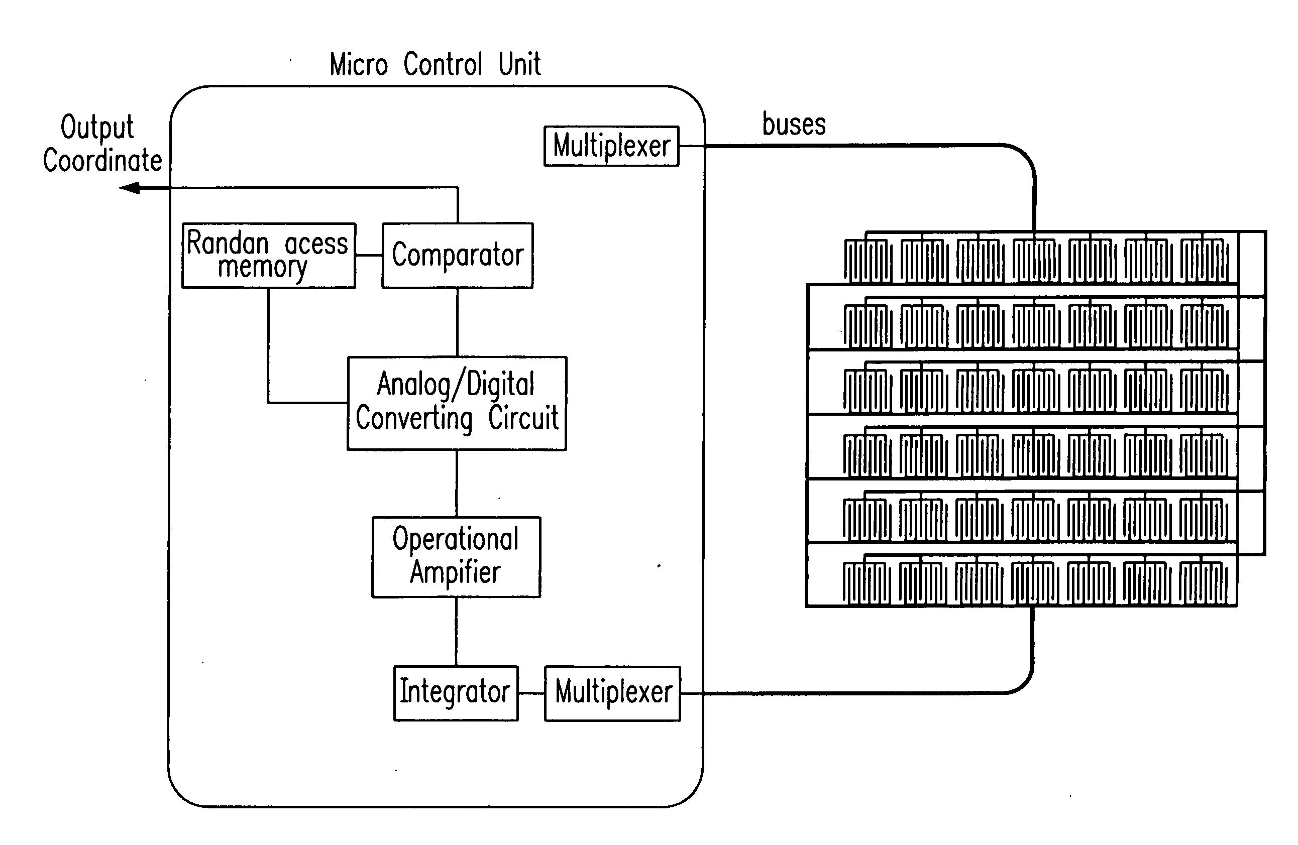
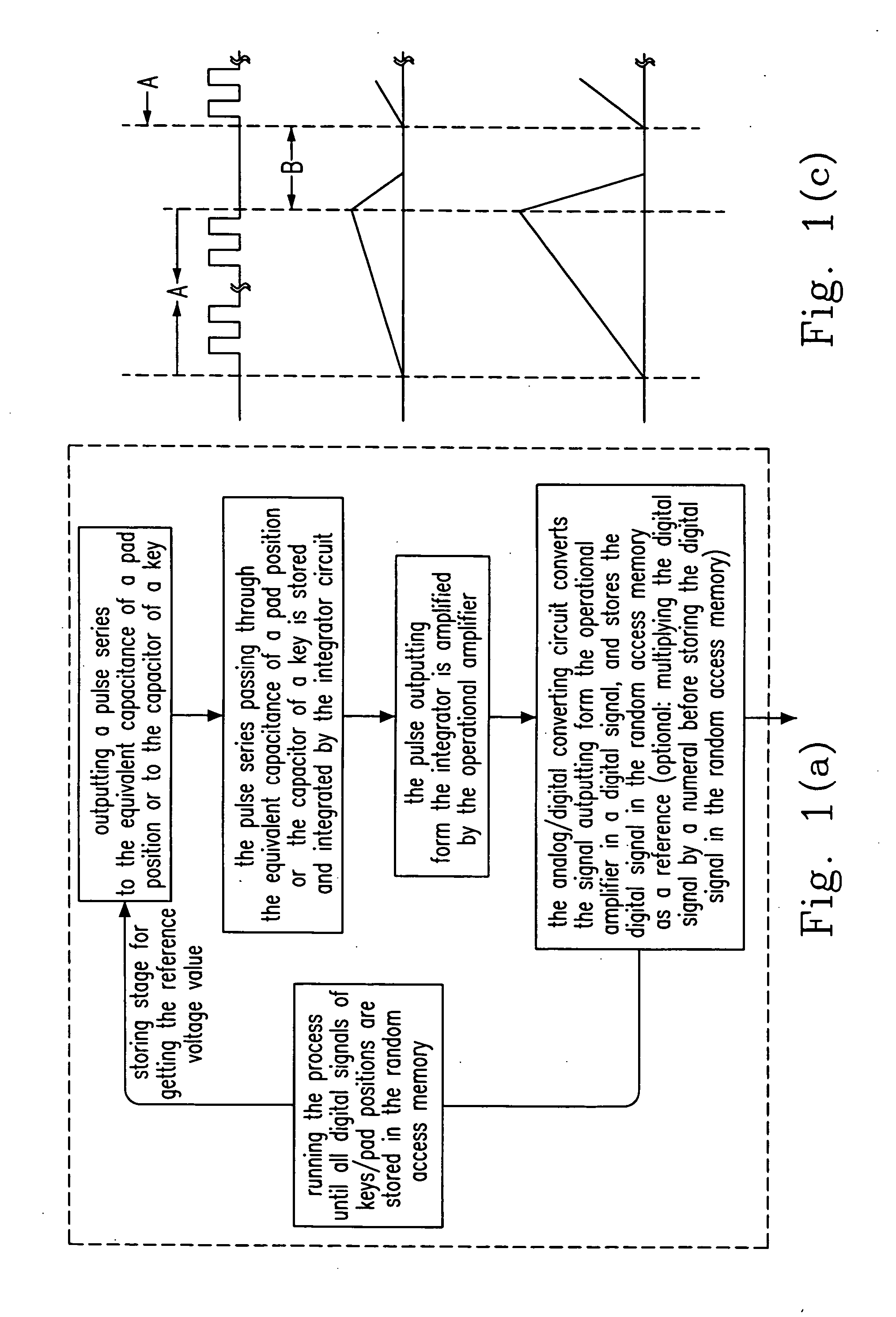
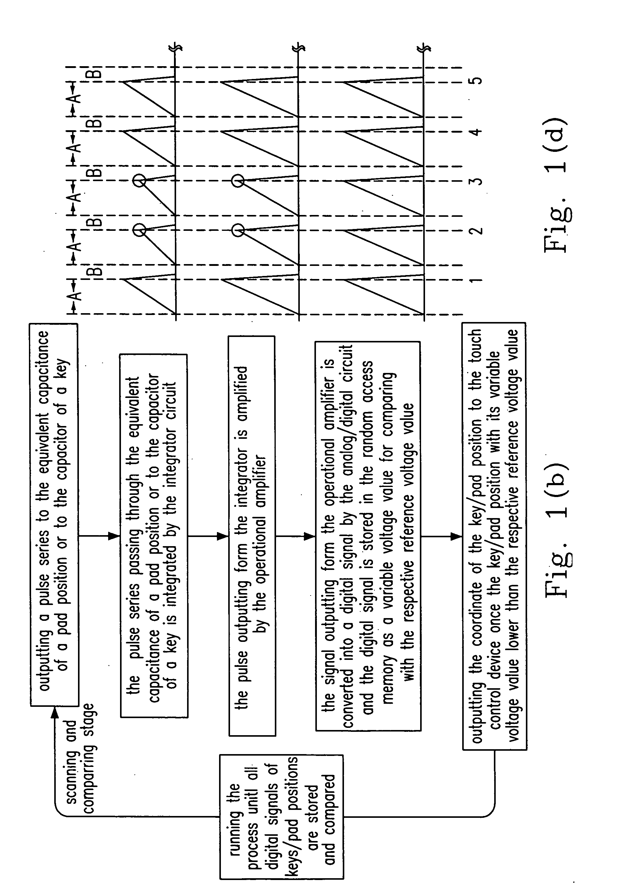
[0037] The principle of the present invention is described below. Firstly, the electric potential charged by each key / pad position is stored as its own reference potential, which could be presented as a reference voltage value for the later comparing step. Secondly, when the user touches the key / pad position, the electric potential energy is absorbed by the user's finger and hence the voltage value of the touched key / pad position is lower than the respective reference voltage value, whereby the micro controlled unit in the touch control device would identify the touched key / pad position according thereto.

[0038] Please refer to...


PUM


Abstract

An identification method for a touch control device having a memory and a pad electrically connected to an equivalent capacitance is provided. The provided identification method for a touch control device includes steps of: (a) charging the equivalent capacitance for obtaining a first voltage value; (b) storing the first voltage value in the memory; (c) touching the pad; (d) scanning the pad for obtaining a second voltage value of the equivalent capacitance; and (e) comparing the first voltage value with the second voltage of the equivalent capacitance for identifying a touched position on the pad.

Description

FIELD OF THE INVENTION [0001] The present invention relates to an identification method for a touch control device, and more particular to an identification method for a capacitive touch control device. BACKGROUND OF THE INVENTION [0002] Generally the systemic design for a touch control device is divided into two types: the capacitive touch control device and the resistive touch control device. Take a common capacitive touch control device for example, for identifying which key / pad position of the device is touched, firstly the electric potential energy charged for a specific key / pad position is recorded while the device is activated. The recorded electric potential is regarded as a no-touch electric potential. After the “touch” action is done, the device identifies whether the key / pad position is touched by comparing the electric potentials charged for each of the keys / pad positions with the no-touch electric potential. The key / pad position with a relative lower electric potential,...

Claims


Application Information

Patent Timeline
Patent Type & Authority Applications(United States)
IPC IPC(8): G09G5/00G06F3/033G06F3/0354G06F3/041
CPCH03K17/962H03K17/9622H03K2217/94031H03K2217/960725
Inventor LIN, YI-CHAN
Owner HOLTEK SEMICON
Why Eureka
Try Eureka