Reflective LCD comprising reflective surface including convex portions whose elevation varying cycles is greater than pitch of convex portions

a liquid crystal display and reflective surface technology, applied in the field of reflection liquid crystal display devices, can solve the problems of deteriorating image contrast, reducing the inclination angle of the reflective surface, and not being stable, and achieve satisfactory optical properties, high contrast, and satisfactory display quality levels

Inactive Publication Date: 2006-06-01
JAPAN DISPLAY CENTRAL CO LTD
View PDF11 Cites 9 Cited by
  • Summary
  • Abstract
  • Description
  • Claims
  • Application Information

AI Technical Summary

Benefits of technology

[0010] The present invention has been developed in consideration of the aforementioned problem, and an object thereof is to provide a liquid crystal display device which can prevent an alignment defect of a liquid crystal without deteriorating a satisfactory optical property and which has a high contrast and a satisfactory display quality level.

Problems solved by technology

A brightness of the external light depends on an installation environment of the liquid crystal display device, and is not stable as in a back light.
However, when the undulation of the reflective surface, that is, a difference of elevation exceeds 1 μm by the aforementioned structure with respect to a small lateral width of about 10 μm, this induces an alignment defect of a liquid crystal, and an image contrast is deteriorated.
However, when such countermeasure is taken, an inclination angle of the reflective surface decreases.
That is, this countermeasure is not practical because the reflection property of the reflective plate is not optimized.

Method used


Image

  • Reflective LCD comprising reflective surface including convex portions whose elevation varying cycles is greater than pitch of convex portions
  • Reflective LCD comprising reflective surface including convex portions whose elevation varying cycles is greater than pitch of convex portions
  • Reflective LCD comprising reflective surface including convex portions whose elevation varying cycles is greater than pitch of convex portions

Examples


first embodiment

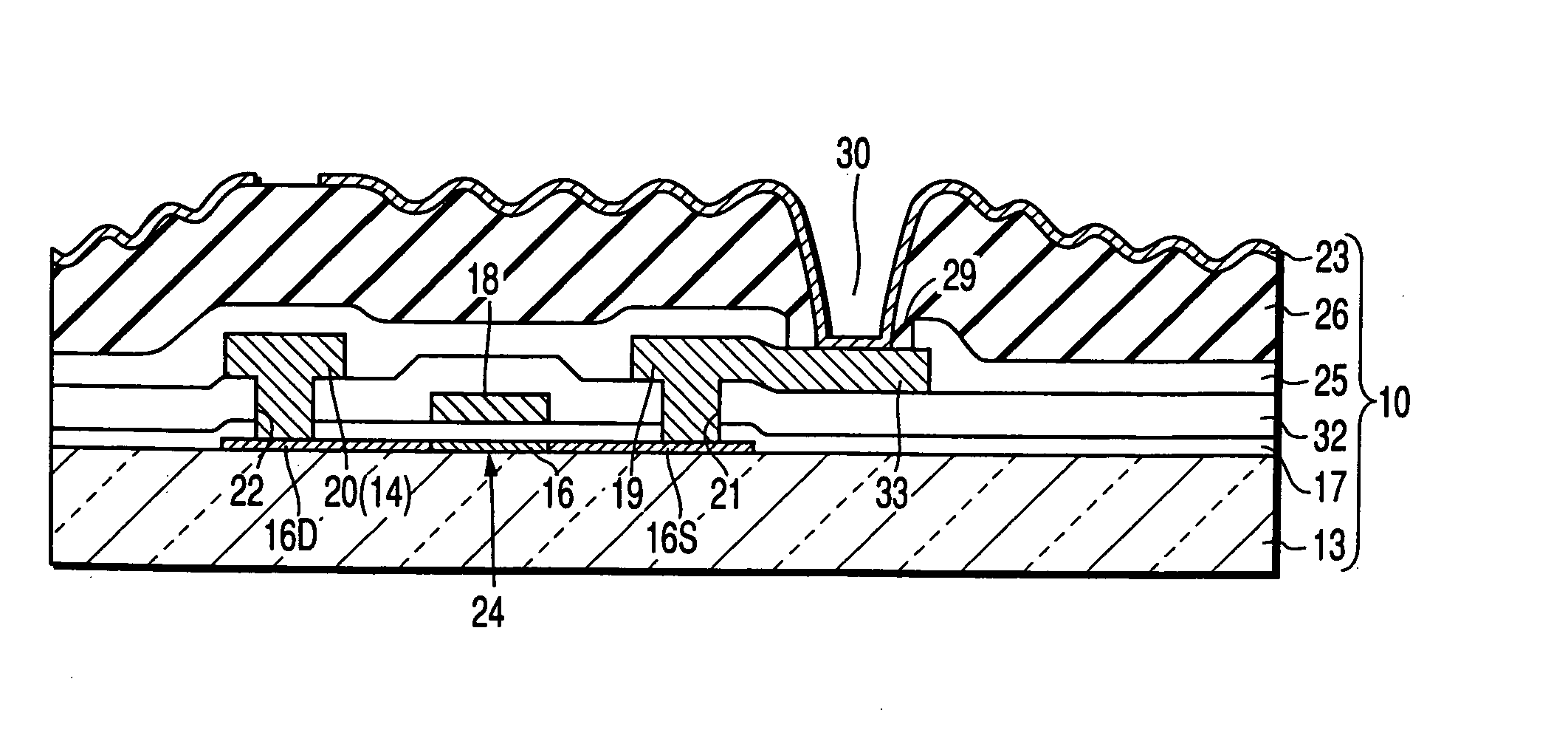
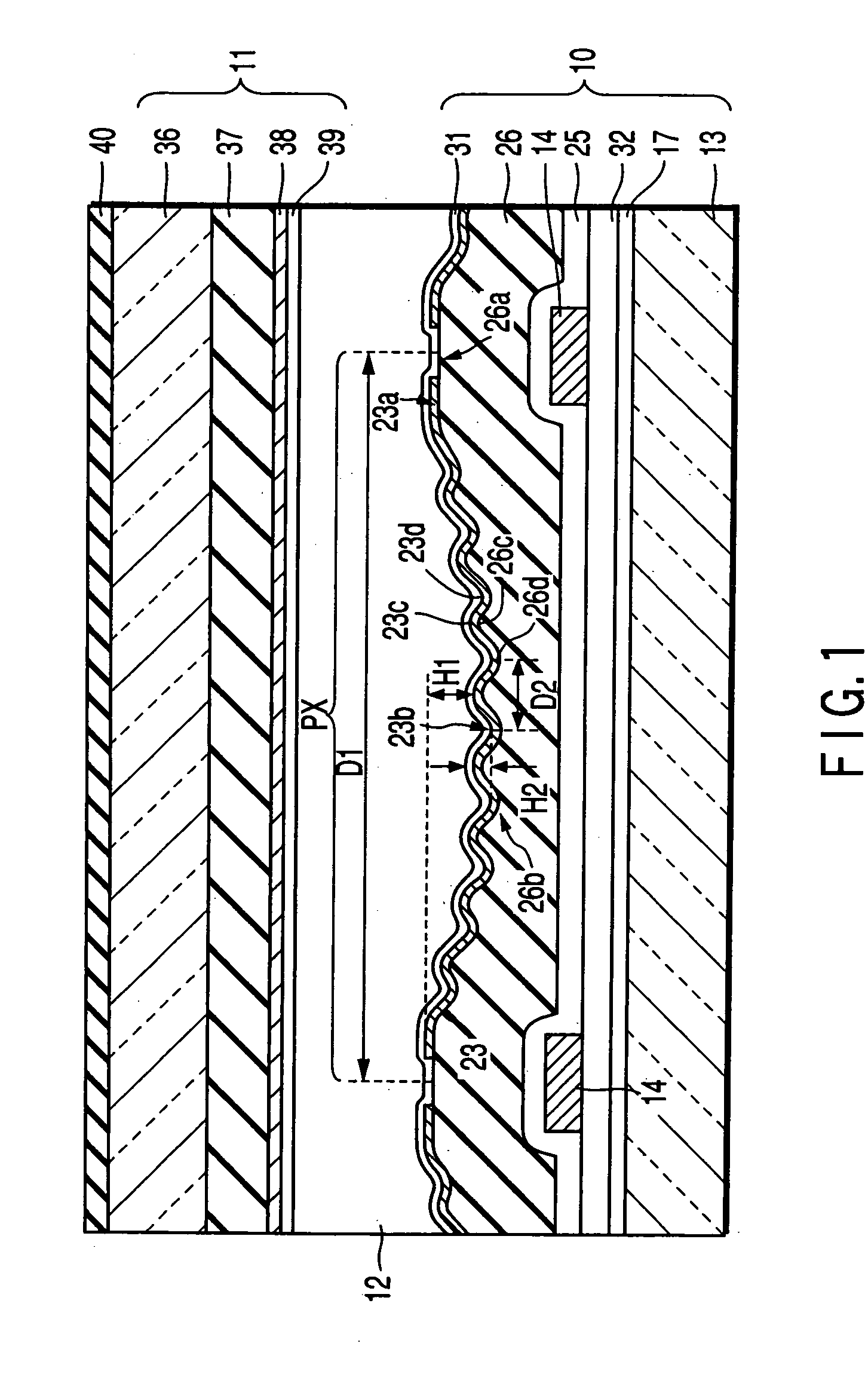
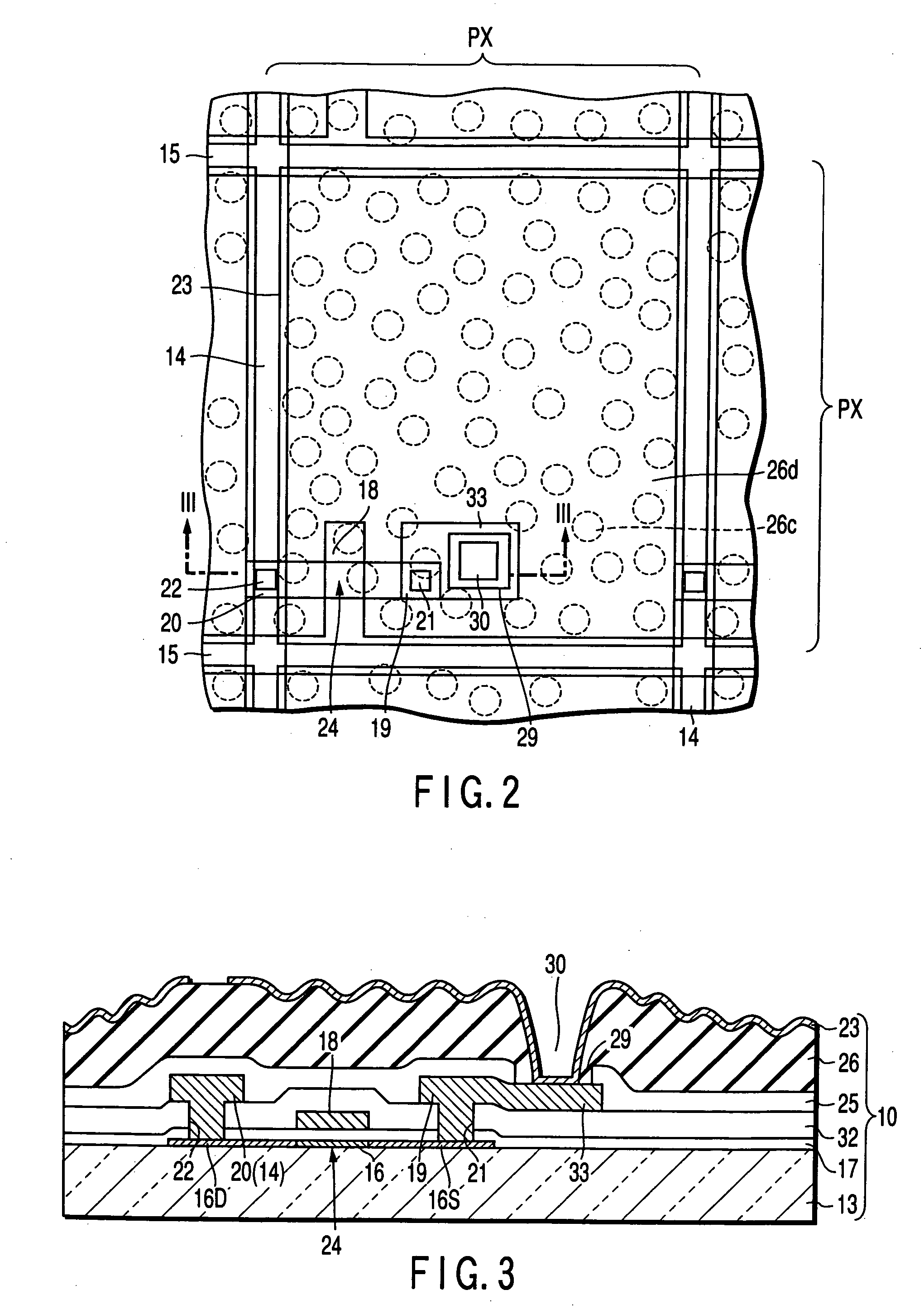
[0038]FIG. 1 shows a sectional structure in the vicinity of a pixel of a reflective liquid crystal display device according to the liquid crystal display device, FIG. 2 shows a plane structure in the vicinity of the pixel of the reflective liquid crystal display device, and FIG. 3 shows a sectional structure taken along line II-II shown in FIG. 2. The liquid crystal display device includes an array substrate 10, an counter substrate 11, and a liquid crystal layer 12 held between these substrates 10 and 11.

[0039] The array substrate 10 includes an insulating substrate 13, a plurality of reflective pixel electrodes 23 arranged in a matrix form, a plurality of signal lines 14 arranged along a row of these reflective pixel electrodes 23, a plurality of scanning lines 15 arranged along a line of these reflective pixel electrodes 23, a plurality of thin film transistors for pixels (TFT) 24 arranged as switching elements in the vicinity of intersection positions of the corresponding scanni...

fourth embodiment

[0089] In the reflective liquid crystal display device of the fourth embodiment, the reflective pixel electrode 23 constitutes the reflective plate, and the reflective surface has a state in which the first undulation having the difference of elevation H1 and second undulation having the difference of elevation H2 are superimposed. The first undulation is constituted of the convex portions 23a arranged along the outer edge in the range of each pixel area PX, and the concave portion 23b surrounded by the convex portion 23a. The second undulation is constituted of a plurality of hemispheric concave portions 23e arranged at random in the range of each pixel area PX, and convex portions 23f surrounding these concave portions 23e. That is, the first undulation is gradually depressed toward the vicinity of the middle from the outer edge in the range of each pixel area PX, and is formed by disposing the gradual inclined surface in the range of each pixel area PX. Moreover, the second undul...

fifth embodiment

[0091] The liquid crystal display device according to the present invention will next be described.

[0092]FIG. 11 shows the sectional structure in the vicinity of the pixel of a semi-transmission type liquid crystal display device, FIG. 12 shows the plane structure in the vicinity of the pixel of the semi-transmission type liquid crystal display device, and FIG. 13 shows a sectional structure taken along line A-B shown in FIG. 12. The semi-transmission type liquid crystal display device includes the array substrate 10, counter substrate 11, and liquid crystal layer 12 held between these substrates 10 and 11. The semi-transmission type liquid crystal display device has a reflection function formed by the reflective plate for scattering the incident light via the counter substrate 11 and liquid crystal layer 12, and also has a transmission function for transmitting the incident light via the array substrate 10.

[0093] The array substrate 10 includes the insulating substrate 13, the plu...


PUM

PropertyMeasurementUnit
heightaaaaaaaaaa
heightaaaaaaaaaa
drain areaaaaaaaaaaa

Abstract

There is disclosed a liquid crystal display device comprising an array substrate, an counter substrate, and a liquid crystal layer which is held between the array substrate and the counter substrate and whose liquid crystal molecular arrangement is divided into a plurality of pixel areas controlled by the array substrate and opposite substrate. The array substrate includes a reflective pixel electrode for scattering a light incident via the counter substrate and liquid crystal layer. The reflective pixel electrode has a reflective surface in which a first undulation having a gradual inclined surface disposed in each pixel area and a second undulation having a plurality of convex portions as main scattering portions disposed in each pixel area are superimposed.

Description

CROSS-REFERENCE TO RELATED APPLICATIONS [0001] This application is a divisional of co-pending U.S. application Ser. No. 09 / 984,291, filed Oct. 29, 2001, and for which priority is claimed under 35 U.S.C. §121. This application is based upon and claims the benefit of priority under 35 U.S.C. §119 from the prior Japanese Patent Applications No. 2000-333722, filed Oct. 31, 2000; and No. 2001-110450, filed Apr. 9, 2001, the entire contents of all applications are incorporated herein by reference in their entireties.BACKGROUND OF THE INVENTION [0002] 1. Field of the Invention [0003] The present invention relates to a liquid crystal display device, particularly to a reflective liquid crystal display device having a reflection function, and a semi-transmission type liquid crystal display device having a reflection function and transmission function. [0004] 2. Description of the Related Art [0005] In recent years, a liquid crystal display device has been applied to various apparatuses such a...

Claims


Application Information

Patent Timeline
Patent Type & Authority Applications(United States)
IPC IPC(8): G02F1/1335G02B5/02G02B5/08G02F1/1333G02F1/1362
CPCG02F1/133553G02F1/136227G02F1/1335
Inventor NAGAYAMA, KOHEIHANAZAWA, YASUYUKI
Owner JAPAN DISPLAY CENTRAL CO LTD
Why Eureka
Try Eureka