Direct exposure apparatus and direct exposure method

a direct exposure and apparatus technology, applied in the direction of photomechanical treatment, printing, instruments, etc., can solve the problems of inability to achieve ideal surface area light sources, inability to sufficiently control the illuminance distribution of light obtained, and increase in production cost and tim

Active Publication Date: 2006-06-01
SHINKO ELECTRIC IND CO LTD
View PDF1 Cites 29 Cited by
  • Summary
  • Abstract
  • Description
  • Claims
  • Application Information

AI Technical Summary

Benefits of technology

[0019]FIG. 1 is a block diagram showing the basic functional configuration of the direct exposure apparatus according to the present invention. The direct exposure apparatus 1 having a light source 2 for projecting light onto an exposure target or more specifically an exposure target substrate 3, comprises: a measuring means 11 for measuring the illuminance distribution of light on an area corresponding to the exposure surface of the exposure target substrate 3; and a control means 12 for controlling, based on the measurement result supplied from the measuring means 11, the light source 2 so that the intended illuminance distribution can be obtained. The intended illuminance distribution here refers, for example, to a uniform illuminance distribution that does not vary depending on the position.

Problems solved by technology

Further, if the wiring pattern is changed or damaged, a new photomask must be produced.
The resulting increase in production cost and time imposes a greater burden on the fabrication process of the wiring substrate.
With the above-described approach that uses the reflecting plate in order to provide uniform illumination over the entire surface of the exposure target substrate, it is difficult in practice to produce an ideal surface-area light source because the light source 2 is not an ideal point light source.
That is, with the feedback circuit alone that each individual laser diode has, it is not possible to sufficiently control the illuminance distribution of the light obtained from the surface-area light source constructed from a two-dimensional array of laser diodes.
With this technique, however, once the surface-area light source has been constructed, it is difficult to make readjustments thereafter; furthermore, it is not possible to flexibly accommodate future changes in exposure conditions, etc.
On the other hand, in the case of the technique disclosed in Japanese Unexamined Patent Publication No. 2002-367900, as the tilt angle of each micromirror is controlled not only according to the amount of light falling on the surface of the exposure target substrate but also according to the pattern data generated for forming the wiring pattern, generation of data for controlling the tilt angles of the micromirrors becomes very complex.

Method used


Image

  • Direct exposure apparatus and direct exposure method
  • Direct exposure apparatus and direct exposure method
  • Direct exposure apparatus and direct exposure method

Examples


first embodiment

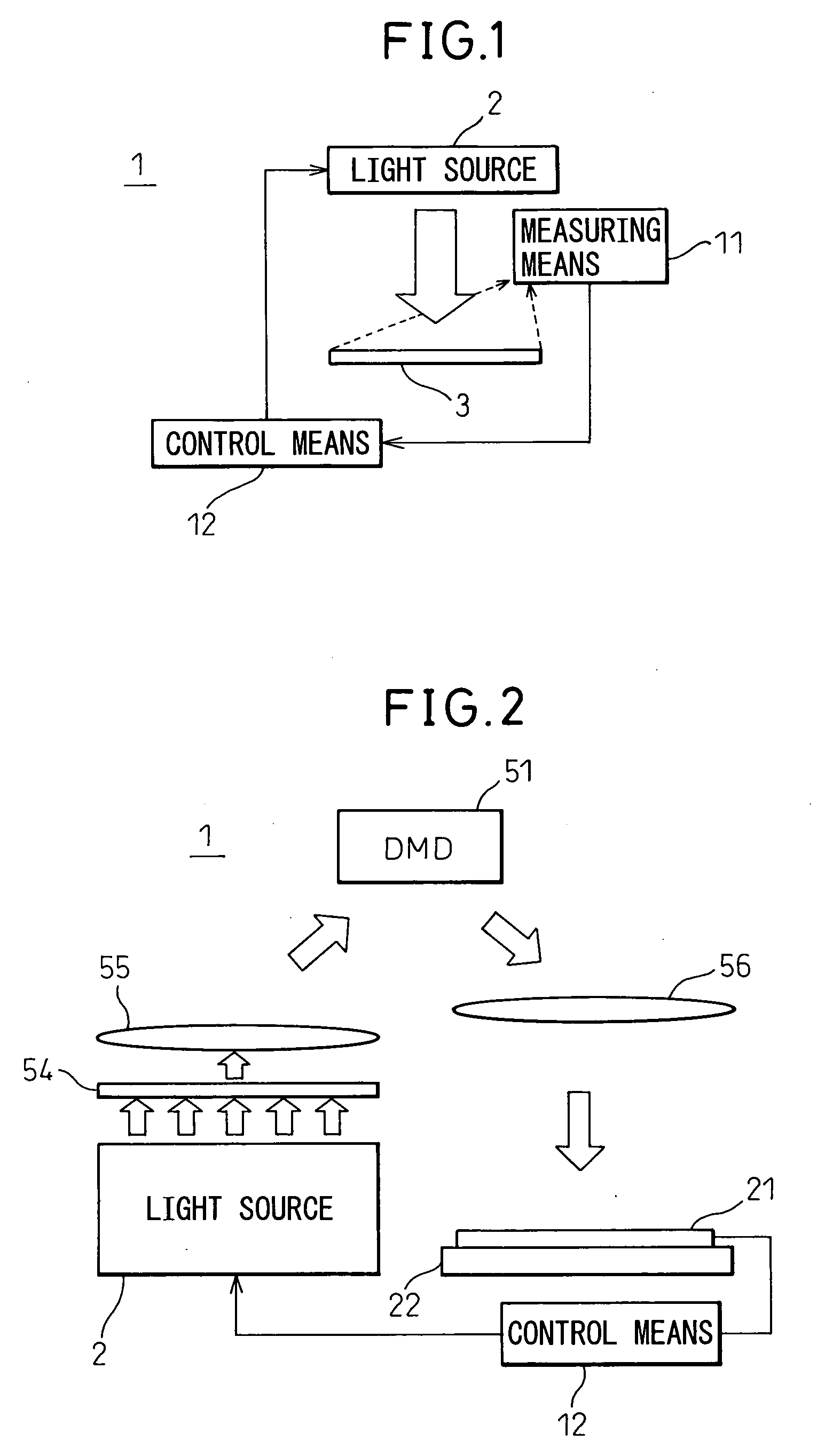
[0046]FIG. 2 is a diagram schematically showing the configuration of a direct exposure apparatus according to the present invention.

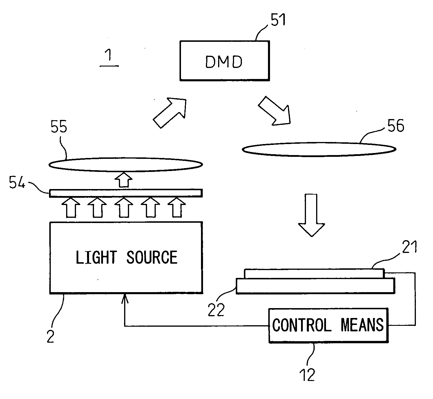
[0047] The direct exposure apparatus according to this embodiment includes a sensor 21 as the measuring means 11 explained with reference to FIG. 1, which measures the illuminance distribution of light on an exposure surface equivalent to the exposure target substrate before starting the exposure of the exposure target substrate. In the present embodiment, the light source 2 is constructed as a surface-area light source by arranging a plurality of point light sources or more specifically laser diodes (not shown) in a two-dimensional array. The DMD 51, diffusing plate 54, and lenses 55 and 56 are the same as those described with reference to FIG. 19. Reference numeral 22 indicates a stage on which the exposure target substrate is mounted for direct exposure. In FIG. 2, the position sensor and the pattern generator are omitted.

[0048] In the present embod...

second embodiment

[0096]FIG. 18 is a diagram schematically showing the configuration of a direct exposure apparatus according to the present invention.

[0097] The process according to the first embodiment of the present invention has been performed before mounting the exposure target substrate on the stage, that is, before starting the exposure of the exposure target substrate. By contrast, the process according to the second embodiment of the present invention is performed during the actual exposure process, and the illuminance distribution of the light falling on the exposure target is measured in real time so that the result of the measurement is immediately reflected in the light source control.

[0098] The direct exposure apparatus according to the second embodiment of the present invention includes, as the measuring means 11 described with reference to FIG. 1, a half-silvered mirror 23 for separating a portion of the light projected toward the exposure target substrate 3 during the exposure proce...


PUM


Abstract

A direct exposure apparatus having a light source for projecting light onto an exposure target or, more specifically, an exposure target substrate, comprises: measuring means for measuring the illuminance distribution of light on an area corresponding to the exposure surface of the exposure target substrate; and control means for controlling, based on the measurement result supplied from the measuring means, the light source so that the intended illuminance distribution can be obtained.

Description

BACKGROUND OF THE INVENTION [0001] 1. Field of the Invention [0002] The present invention relates to a direct exposure apparatus having a light source for projecting light onto an exposure target or, more specifically, an exposure target substrate, and a direct exposure method for exposing the exposure target substrate by projecting light from the light source onto the exposure target substrate. [0003] 2. Description of the Related Art [0004] Generally, a wiring pattern on a wiring substrate is formed by exposing the substrate based on design data defining the wiring pattern and by developing and printing the desired pattern on the substrate, followed by etching. In one exposure method as an example, the exposure is performed using a photomask. In this method, a photosensitive resin is applied over a substrate fabricated by bonding metal foil as a conductive layer onto an insulating material, and a photomask with the desired wiring pattern written thereon is placed over it. By expos...

Claims


Application Information

Patent Timeline
Patent Type & Authority Applications(United States)
IPC IPC(8): G03B27/72
CPCG03F7/2057G03F7/70141G03F7/70666
Inventor SEKIGAWA, KAZUNARISAMIZU, HIROAKIINOUE, TAKAHIRO
Owner SHINKO ELECTRIC IND CO LTD
Why Eureka
Try Eureka