Underwater exterior ship hull imaging system employing a remote microprocessor controlled acoustic transducer array

a technology of acoustic transducer array and an underwater imaging system, which is applied in the direction of using reradiation, measuring devices, instruments, etc., can solve the problems of increasing the inspection process of the underwater vessel, increasing the inspection cost and time, and increasing the cost and labor. cost and labor intensity, and achieves high resolution and optimal and redundant coverage

Inactive Publication Date: 2006-06-01
HULL UNDERWATER IMAGING SYST
View PDF13 Cites 16 Cited by
  • Summary
  • Abstract
  • Description
  • Claims
  • Application Information

AI Technical Summary

Benefits of technology

[0012] Each orthogonal array consists of a first transducer mounted to a stationary member for transmitting continuous sonar pulses along a horizontal plane and a second transducer mounted to the same stationary member for transmitting continuous sonar pulses along a vertical plane such that the two beaming sonar pulses are orthogonal, thereby providing optimal and redundant coverage. Multiple transducer pairs are employed along the stationary member at top and bottom positions within the channel to scatter acoustic waves from multiple positions as a ship passes through the channel. The acoustic transducer array system utilizes echolocation for imaging a ship's hull, displayed on a monitor or printer, by emitting sound waves and analyzing the waves reflected back to the sender by the ship's hull through a microprocessor controlled central unit and processor suite. In particular, reflected signals received back from the ship by the transducers are transmitted to a central processing unit (CPU) and imaging unit which integrates the signals into electrical data to create a visual image on the monitor utilizing a software rendering program. The rendered image of the underwater hull produced by the CPU and imaging unit from the transducer signals is an enhanced, high resolution, three dimensional image of the ship hull, whereby features of the hull's configuration, such as intakes, anodes, keel coolers, and stabilizers, just to name a few, would be revealed and establish a baseline for providing Homeland Security, law enforcement, and port personnel with the necessary data needed to determine whether a ship hull is suspicious in appearance warranting detention, whereby the stored digital image could be used for future analysis and comparisons upon return transits. The enhanced image, produced by my novel transducer array system, provides an additional level of security for detecting hull anomalies, which, upon further inspection, may prove to be chemical and / or biological agents, explosive devices, or other contraband materials.

Problems solved by technology

Inspection of a ship's interior spaces requires the use of scent dogs, inspection personnel and / or electronic devices, all of which are cost and labor intensive.
Inspection of the underside of a submerged vessel is an even more difficult task, particularly since these ships, at a minimum, are more than several hundred feet long and draw between ten to twenty-five feet, depending on whether they are loaded with cargo.
One drawback to this type of prior art system is that manpower is required to record every square inch of the submerged hull, thereby adding expense and time to the inspection process of the vessel.
Other factors, such as environmental conditions can also have detrimental effects on the quality of the recordings and include water clarity, water temperature, and salinity.
This prior art process is clearly inadequate and antiquated for today's needs in border protection, control, and inspection.
However, a limitation to sonar is the Doppler Effect which occurs with sound waves.
In underwater sonar, the Doppler Effect can attenuate sound waves and cause distorted imaging thereby playing havoc on the desired results.
This type of transducer would not be suitable for inspecting objects such as large freight tankers.
This device does not employ sonar technology and is greatly inhibited by poor water quality in the same way that divers are inhibited during inspection dives.
Furthermore, a remote operated vehicle requires extensive training, manpower and support to operate and to maintain the vehicle and is therein inadequate for today's needs.
The image produced by this prior art device is limited to a pictorial diagram and does not contain the high level of detail desired for a thorough and accurate representation of a ship's hull.
These devices too are inadequate for today's needs since they are incapable of producing a clear image of the ship hull as it passes by the transducers.

Method used


Image

  • Underwater exterior ship hull imaging system employing a remote microprocessor controlled acoustic transducer array
  • Underwater exterior ship hull imaging system employing a remote microprocessor controlled acoustic transducer array
  • Underwater exterior ship hull imaging system employing a remote microprocessor controlled acoustic transducer array

Examples


Embodiment Construction

[0022] Throughout the following detailed description, the same reference numerals refer to the same elements in all figures.

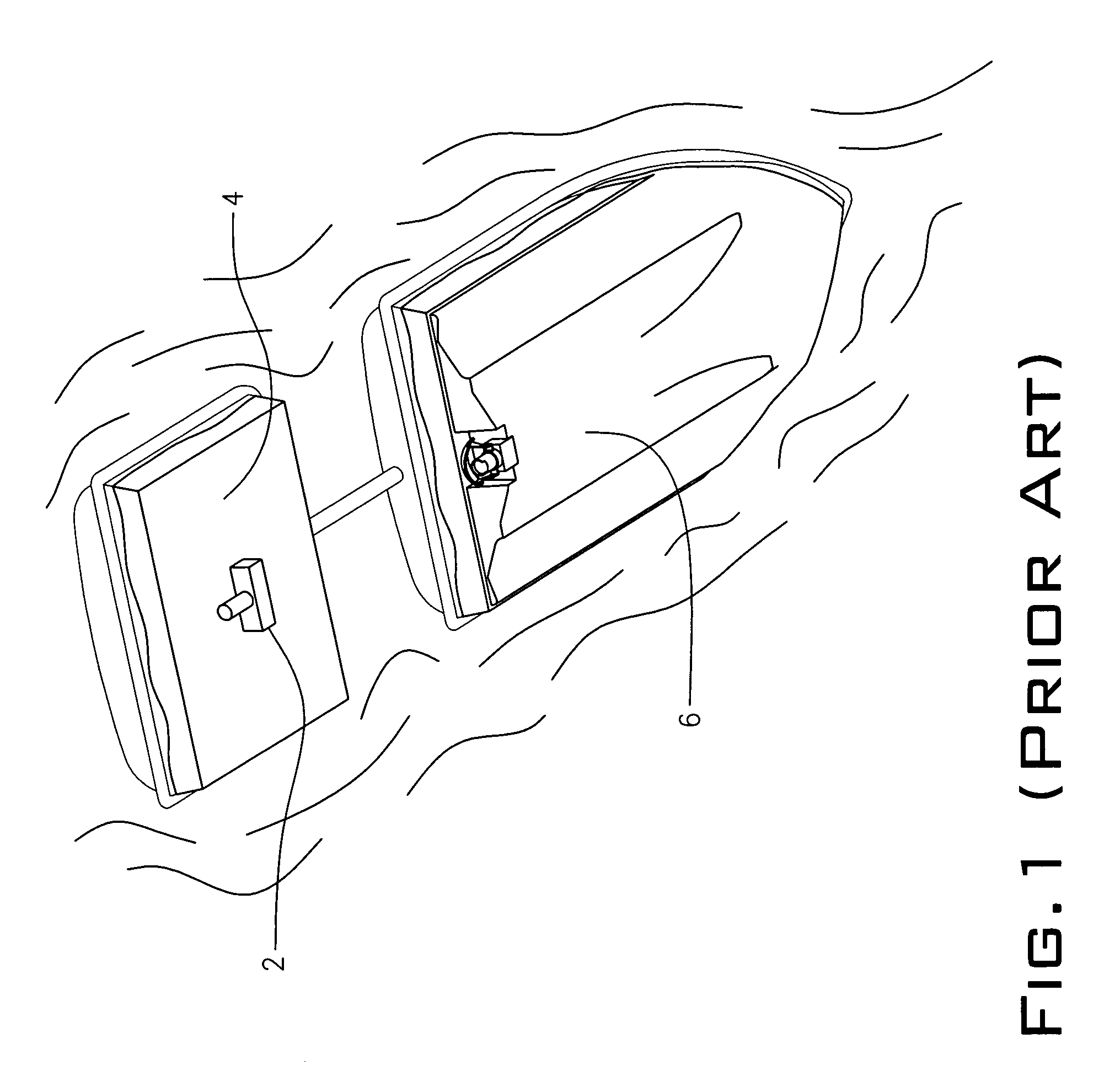
[0023] Referring to FIG. 1, a prior art sonar device is shown. In such device, a transducer 2 is mounted on a bottom side of a platform 4. The platform 4 is attached to a stern portion of a boat 6 and towed from behind and is used to map ocean and seabed floors. To do such, transducer 2 propagates a sonic pulse downwardly and records a signal from the pulse when it is reflected off the ocean or seabed floor (not shown). The device of FIG. 1 is not used in the imaging of boat hulls as in the present invention. However, transducer 2 is an example of one acoustic transducer that can be employed as one of a pair in the present invention of an array of transducer pairs.

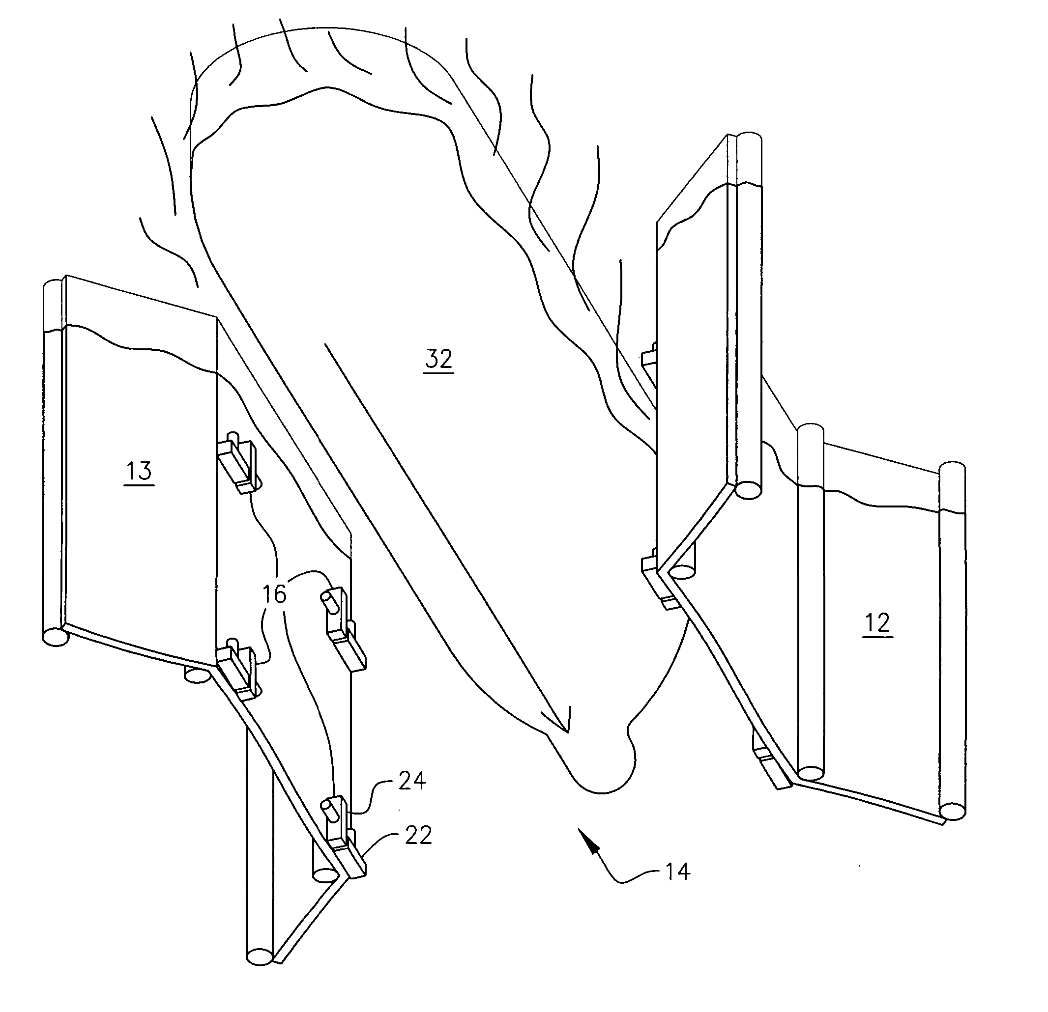
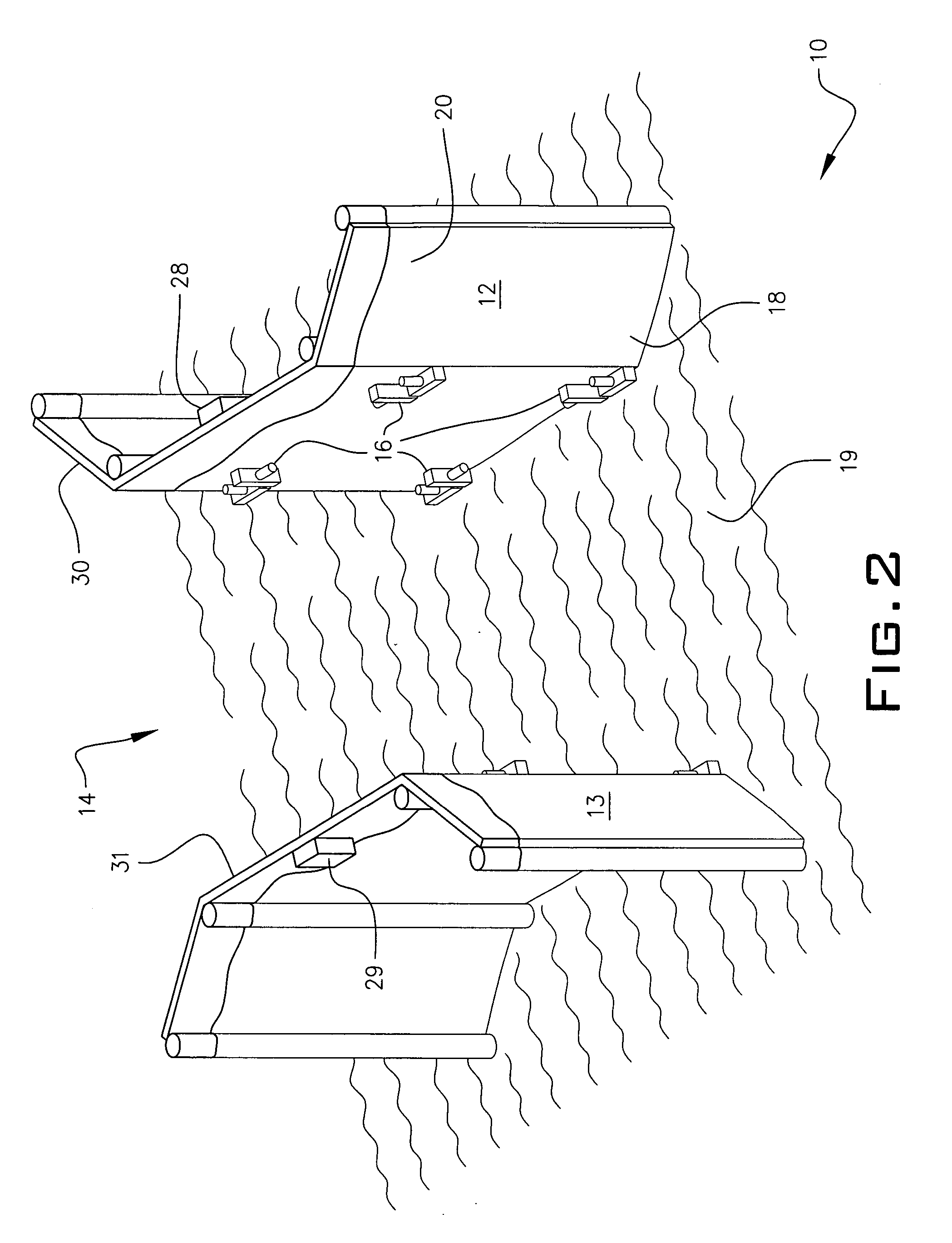
[0024] Referring to FIGS. 2 and 3, a stationary multi-beam transducer array 10 is positioned on a first and second fender wall, 12 and 13 respectively, along each side of a shipping channel 14 (fend...


PUM


Abstract

A multi-beam acoustic transducer array system for producing color enhanced, three dimensional, high resolution images of a ship's underwater hull, wherein the acoustic transducers can be mounted in orthogonal pairs, each pair being positioned opposite from another pair within a shipping channel. The array can be utilized either in a stationary configuration within a controlled shipping lane or suspended in the water column from a mobile support vessel, with at least one array being orthogonally mounted and suspended in the water column from the mobile support vessel, wherein the mobile configuration obviates the need for multiple orthogonal arrays, for purposes of performing acquisition and imaging of a ship's hull. Each orthogonal array consists of a first transducer transmitting sonar pulses along a horizontal plane and a second transducer transmitting sonar pulses along a vertical plane, such that the two beaming sonar pulses are orthogonal, thereby providing optimal coverage.

Description

BACKGROUND OF THE INVENTION [0001] 1. Field of the Invention [0002] The present invention relates to a method for imaging an exterior ship hull while underway or anchored using a remote sensing multi-beam sonar system array. More particularly, it relates to a multi-beam sonar array wherein a plurality of acoustic transducers are installed either in a shipping channel in a configuration that permits a ship's hull to be imaged while in transit through a channel or while the ship is stationary in an anchorage. [0003] 2. Description of the Prior Art [0004] The capability to inspect the underside of freight ships and large vessels has always been of great concern for ports of entry, ports of call, and country port borders. It is well known that ships such as these have been frequently used to smuggle illegal drugs and contraband through ports of entry. This concern has been elevated in recent years as the focus has shifted to include nuclear, chemical, and / or biological agents, explosive...

Claims


Application Information

Patent Timeline
Patent Type & Authority Applications(United States)
IPC IPC(8): G01S15/89G01S15/00
CPCG01S15/89G01S7/6245
Inventor ROGERS, MARK S.
Owner HULL UNDERWATER IMAGING SYST
Why Eureka
Try Eureka